Shared Knowledge
"AT&T Home Security System - Wireless Keypad is Not Working"
22 November 2011
Summary: while it possible that a component on the wireless keypad circuit board has gone bad, it is more likely that: a wire has come loose; a dipswitch has been misaligned or a ribbon cable needs to be reseated into the circuit board socket. All can be fixed do-it-yourself (DIY).
Background:
My definition of a non-working AT&T home security system wireless key pad: completely dead; will not arm or disarm the system; causes false alarms.
The possible, non-circuit board failure, causes of a non-working AT&T home security system wireless keypad include:
- Battery connection broken at battery connector or on back side of circuit board.
- House code wires (3) dislodged from circuit board pins.
- Tamper switch metal arm distorted or bent out of shape.
- Wires from circuit board to back plate broken.
- Magnetic reed switch wires (if keypad attached to reed switch) broken or loose.
- Ribbon cables need to be reseated in circuit board connectors.
To avoid alarms while working on keypad:
If your AT&T home security system is still being remotely monitored, call your monitoring company and tell them you are going to work on system.
Go to the central controller (CC) and loosen the 2 screws holding the plastic face onto the CC chassis (small flat blade screwdriver).
Remove face plate.
Unhook red wire from the internal battery.
Unplug the CC's power adapter from the power outlet. The adapter might be attached to the outlet via a screw you might have to loosen or remove (Phillips screwdriver),
The CC should be dead.
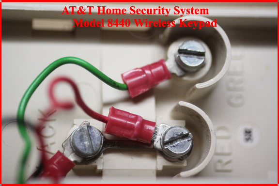
Back plate wires:
Go to the faulting wireless keypad and open it off the base plate.
Check that the black, green and red wires are attached to the terminals shown below. If not, do what you have to do to get circuit board wires connected back to back plate terminals.
If your wireless keypad is connected to a magnetic reed switch, make sure the 2 wires from the switch connect to the green and red back plate terminals.
If the reed switch wires are loose or no longer properly connected, do what you have to do to get the switch properly connected to the back plate terminals.
If your wireless keypad is connected to a magnetic reed switch, is switch firmly attached to door jam or window molding? Is the magnet firmly attached to the door or window frame and directly opposite the reed switch? Over time, the reed switch and or, door magnet came become loose causing false alarms.
If you must replace the reed switch, you need the type is that "normally closed (NC)", meaning that when the magnet is directly opposite the switch, the reed switch will appear as a closed connection to the wireless keypad. Opening the window or door will break the connection.
Now loosen the red, green and black wires and remove the wireless keypad from the back plate.
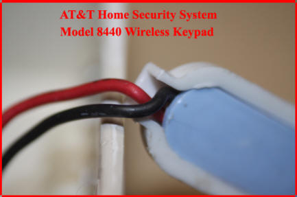
Battery connection:
Now check the battery connector. Are the black and red wires firmly in the connector?
Battery changes are tough on the connector and wires. I have seen many wireless keypads with replaced battery connectors.
Dumb question, but 9volt battery is good?
If your wireless keypad is completely dead, with a fresh battery firmly attached to wireless keypad battery connector, use a voltmeter to check voltage right on the wireless keypad circuit board.
Other than a voltmeter, I can not come up with a good way to test that there is 9volts getting to the circuit board.
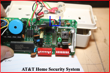
In the image below, bounded by blue, you will see where the red and black wires from the battery attach to the circuit board. If you do not have 9volts reading here, there is a problem with either the battery connector or the wires from the connector to the circuit board or the wires are not properly soldered into/onto the circuit board.
Replacement battery connectors with wires are available at Radio Shack or over the Internet.
There is no good way other than soldering to get either new wires attached to the circuit board or tacking down loose but otherwise good battery wires.
Circuit board dipswitches:
On the AT&T home security system wireless keypad, 2 sets of dipswitches are used to: (1) define the house ID in use and (2) set a unique device ID.
"House ID". As it is possible that AT&T home security systems were installed in a all houses of a neighborhood, each house had to have its own, unique, house ID. The "House ID" was set inside the CC via dipswitches and then all devices used in that home had the same house ID set in the device's "House ID" dipswitches.
As each device in an AT&T home security system transmits a signal to the CC, the CC needs a way of knowing which device is alarming or reporting trouble and this is down via a unique device ID set in dipswitches on device circuit boards.
An AT&T home security system can support 31 different wireless devices.
In the image below, the first set of red dipswitches hold the device ID of the device.
Dipswitches 1 through 5 are either set to "On" or "Off" to define a binary number and its decimal equivalent.
The second set of red dipswitches holds the "House ID or Code".
7 switches, set to either "ON" or "Off" define a binary number and its decimal equivalent.
Although not likely, it is possible that either the device ID or the House ID got changed during a battery change or device move.
If you do not know your home's "House ID", go to the CC and find the red dipswitches and copy down the switches "On" and "Off" positions.
Now compare the CC's define "House ID or Code" to what is defined in the wireless keypad.
If the 7 dipswitches of the wireless keypad match the first 7 switches of the CC, the "House ID or Code" is set correctly in the wireless keypad.
If a switch is out of position, use a pencil point to move the incorrect dipswitch(es) to the correct position.
No 2 devices in the AT&T home security system can have the same "Device ID".
You should have a card somewhere that was prepared by the installing showing which ID is associated with which a defined physical location device.
The device ID card will show decimal numbers from 0 through 31.
The decimal number achieved by summing the binary valves of all device ID dipswitches set to "OFF" should match the installer ID card.
Binary values.
Dipswitch 1 can either have a value of 0 or 1. It has a value of 1 when the switch is "Off".
Dipswitch 2 can either have a value of 0 or 2. It has a value of 2 when the switch is "Off".
Dipswitch 3 can either have a value of 0 or 4. It has a value of 4 when the switch is "Off".
Dipswitch 4 can either have a value of 0 or 8. It has a value of 8 when the switch is "Off".
Dipswitch 5 can either have a value of 0 or 16. It has a value of 16 when the switch is "Off".
So if the device ID card says the wireless keypad you are working on has a decimal value of 20, this means:
Dipswitch 1 is "On" = 0
Dipswitch 2 is "On" = 0
Dipswitch 3 is "Off" = 4
Dipswitch 4 is "On" = 0
Dipswitch 5 is "Off" = 16
For a decimal total of 20 as defined by the device ID card.
If the dipswitches that define the device ID do not match what is on the installer card, move the applicable dipswitch with the end of a pencil, either "Off" or "On".
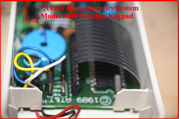
Arm/Disarm code wires:
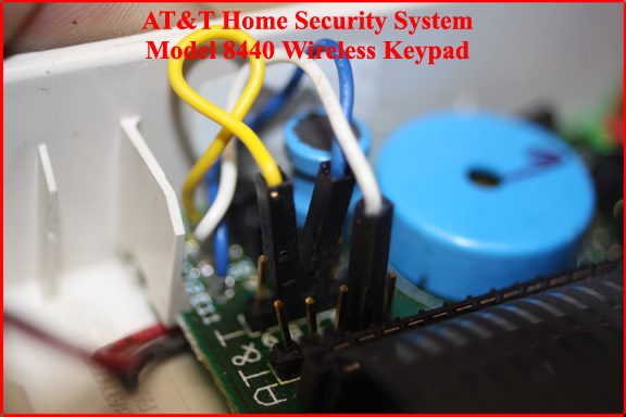
There are 3 wires used to define the 3 digit arm/disarm code.
Unfortunately, these 3 wires are located near the battery compartment and thus could be disturbed during a battery change.
The 3 wires are color coded: blue, white and yellow.
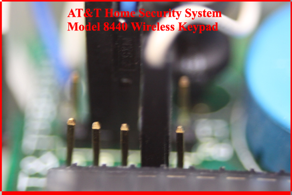
These 3 wires are pushed down over electrical pins sticking out of the 8440 circuit board.
If any of the 3 wires is loose or not connected to a pin, refer to AT&T Home Security System - Changing the Home Security Code.
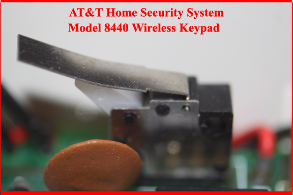
Tamper micro switch:
To ensure a burglar can not simply open a wireless keypad or universal transmitter, there is a tamper micro switch installed on the circuit board.
When the wireless keypad is properly latched into the back plate and the tamper switch metal arm has not been bent or otherwise damaged, the metal arm of the tamper switch presses against the back plate, closing a circuit.
If the tamper switch metal arm has been bent down, when the wireless keypad is closed on the back plate, the tamper switch might not be closed properly or it might be ok most of the time but then sound a false alarm due to an adjacent door opening and closing repeatedly.
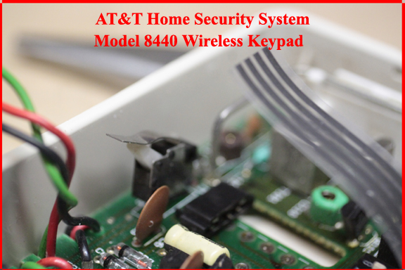
In the image below, the tamper switch is shown with the metal arm appearing as it should be.
If your arm is not as shown bend it to match the image below.
Also check that the tamper switch is firmly attached to the circuit board. I have seen some tamper switches that have been partially pulled out of the circuit board. If the tamper switch is not firmly attached to the circuit board, you might have to push it back down into the circuit board and do some soldering work.
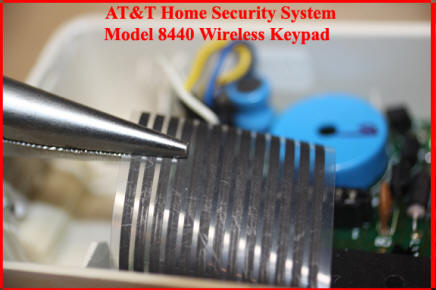
Ribbon cables:
The actual numeric keypad on the front of the AT&T home security system wireless keypad connects to the circuit board via a flexible ribbon cable.
Ribbon cables are great but the actual metal contact of the ribbon that fits into the circuit board connector can become contaminated by house pollution and the might have to be removed from the circuit board connector and then reseated.
If you are having trouble getting your AT&T home security system to arm and/or disarm and the arm/disarm code is properly set via the blue, white and yellow wires, then the most likely problem is the numeric keypad ribbon cable.
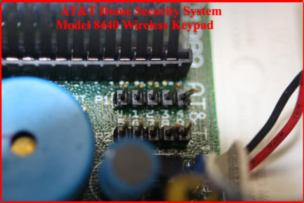
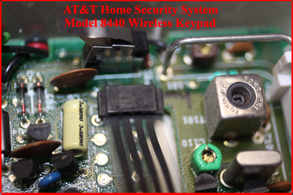
The image below shows the numeric keypad ribbon cable inserted into the circuit board connector.
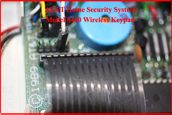
To remove the ribbon cable from the connector, you can use your finger under the cable, right at the connector and push upward or you can grasp on edge of the ribbon cable and lift up. The ribbon cable will easily come out of the connector
Although not necessary in most cases, you can try to gently clean the edge of the ribbon cable by using a soft pencil eraser.
To reinsert the ribbon cable into the circuit board connector, you probably are going to need a pair of needle nose pliers.
With one side of the cable inserted into the circuit board connector, move the pliers to the other side and insert that side of the cable.
Using he pliers, make sure the ribbon cable is all the way down into the circuit board connector.
"Home", "Away" and "Off" buttons ribbon cable:
The AT&T home security system wireless keypad 8440 has buttons for "Home", "Away" and "Off".
The AT&T home security system wireless keypad 8420 does not have "Home", "Away" or "Off" buttons but uses a slide switch as part of the circuit board to accomplish the same arm/disarm functions as the 8440 buttons.
On the model 8440 wireless keypad, the "Home", "Away" and "Off" buttons are connected to the circuit board via a ribbon cable.
As mentioned above, over time, this cable can become slightly dislodged from the circuit board connector or the contacts between the cable and the connector become fouled by indoor air pollution.
In the case of the 8440 function buttons, the ribbon cable can be easily pulled out of the circuit board connector.
To reinsert the function buttons ribbon cable into the circuit board connector, simply align the cable and the connector and push.
You might have to push in one side and then the other.
Once the cable is seated, make sure it is pushed all the way down into the connector, all across the width of the cable.