Shared Knowledge
"AT&T Home Security System - Details of the Central Controller (CC)"
12 December 2009
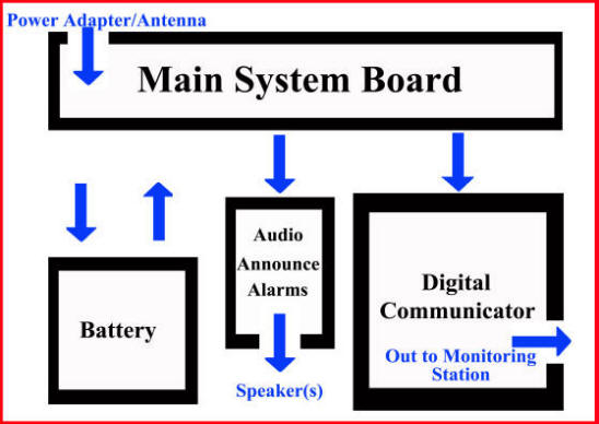
Main system board functions:
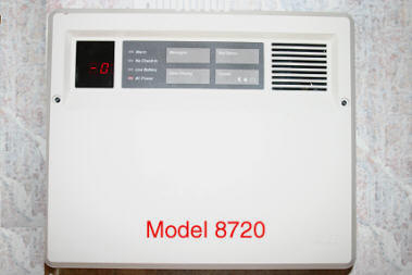
The main system board is actually hidden from view and is under the black plastic panel running along the top of the CC. You can get to this panel, if you wish, by using a flat blade screw driver to unlatch case tabs (pry the tab outward slowly) holding the board to the case at 2 of the 4 points on the case and then by lifting upwards on the board. Please note that there is a flat ribbon cable connecting the main board to the "buttons" on the black plastic cover. This ribbon cable is very short and can be difficult to reinsert into the board connector without using needle nose pliers.

Functions of the CC's main circuit board include:
- System power management. This includes accepting 16VAC in and converting to 12VDC for various system devices such at the "digital communicator", audio announcer board, sirens and for trickle charging the backup battery. It also detects the lost of main power and switches over to using the battery.
- System control and status display. This board, via the touchpad and led display, allows for placing the system in various modes as well as displaying system messages or status in the led window.
- Radio receiver. Via this circuit board, the CC listens to all security devices install in the home (universal transmitters installed at windows and doors, smoke detectors, wireless keypads, etc.)
- Holds a system device table. When the CC is started up for the first time or after a system reset, as the CC radio receives a "check-in" message from each security device installed, it creates an entry in a system device table that includes the device number as well as the time of the "check-in". Then, this board examines the device table periodically to make sure it has not been more than 12 hours since a device last checked-in. If a device has not checked-in in 12 hours, the CC reports trouble.
- Arms and disarms the system. Via the receiver, responds to wireless keypad instructions to either arm or disarm the system.
- Trouble reporting. When there is a problem anywhere in security system (no check-in or low CC battery) this board reports trouble via its built-in, loud, beeper.
- Triggers the digital communicator. At a system event, such as intrusion, fire detection, panic, etc, this board triggers the digital communicator and tells it which zone is reporting. The digital communicator then dials the stored telephone number of the monitoring station and reports they type of event or "zone" is responding to.
- Triggers the audio announcer. At a system event such as intrusion or fire detection, this board triggers the audio announcer board, which then announces a message in English to the attached speaker(s).
- Triggers attached siren, if one present. If a siren is present in the system, at a system even requiring a siren (intrusion or fire detection), this board supplies power to an attached siren. (Note that a special board with a relay on it is actually required to be present to support a 12volt, high current siren.)
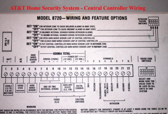
- Note that all signals from CC's main control board are 12VDC (all screw terminals). When there is an event, such as smoke detected or an intrusion, the CC's main control board supplies steady +12VDC to one of the zone terminals and thus to the digital communicator and does so until the CC is "event cleared" via a wireless keypad. Also note that the main control board supplies +12VDC to any attached sirens at a system event (not trouble) but switches the siren power on and off in about a 2 second interval. Siren power is not steady power.
Digital communicator functions:
- Accepts digital programming. This circuit board has what is known as an erasable programmable read-only memory chip (EPROM) that holds information about the system to include: the telephone number of the monitoring station and what and how to report at a system event. The information about monitoring station telephone number, etc is stored in the EPROM because it can not be lost at a system power outage, no matter the time length of the outage. To reprogram the digital communicator's EPROM you must have the model 8710 digital programmer.
- Is an auto dialer. When trigger by the CC's main circuit board at a reportable system event, the digital communicator places a phone call to the monitoring station.
- Is a digital communicator. Once a phone link has been established with the monitoring company, the digital communicator reports, in a digital format, the nature of the problem and which device or "zone" triggered the phone call. (Zones. They are called "zones" but I think of them as system events. An intrusion is 1 zone and causes an audible alarm and monitoring station phone call while a "hostage" or "ambush" is another zone and results in a phone call being placed but no audible alarm in the home.)
Audio announce alarms:
- Holds English language messages in circuit chip(s). ("Buglar. Leave Immediately" or "Fire. Leave Immediately.")
- Audio amplifier driving system attached speaker(s). When a system event occurs that requires an attached speaker announcement, the main circuit board triggers this announcement board and depending on the nature of the even the board responds with the applicable "recorded" message.
Siren control board, if present:
- Closes relay supplying voltage to siren(s). Actual, 12 volt input siren(s) (not speakers driven by siren-sound audio boards) can not be driven by the CC directly (current demand of the siren(s) too much for main circuit board's power converter) but must have their own 12 volt power supply. Thus, at a system event requiring the sounding of an attached high power siren, the main circuit board of the CC supplies 12 volt power to the siren relay, which then closes supplying external 12volt power to siren(s). This small circuit board is nothing more than a 12 volt relay and if you want a high powered siren attached to your system, you should be able to wire in a small 12 volt relay and connect the relay solenoid to the main circuit board siren screw terminals.