Shared Knowledge
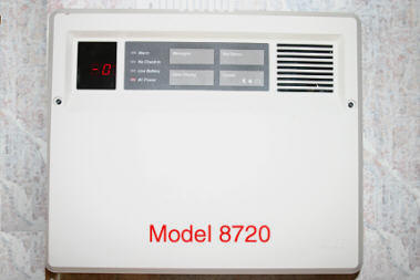
"AT&T Home Security System - Conversion to User Programmer Auto Dialer"
11 December 2009
Updated: 14 Dec 2010
Updated: 15 Dec 2011
Updated 31 July 2012
Summary: the AT&T security system is well designed and the quality of system components is excellent but the monitoring station phone dialer inside the central controller (CC) can not be programmed for phone number changes easily and with the cost of monitoring station services continuing to rise, the system can be, relatively easily, changed so it automatically dials any 10 telephone numbers (including cell phones ) you want.
Background:
The AT&T security system is well designed and the quality of system components is excellent but the phone dialer component inside the central controller (CC) requires a special AT&T programmer to change the phone dialer stored monitoring station phone number(s) and this programmer is very rare. Most monitoring station companies do not have the required programmer tool and if you contact them about your system, they will most likely want you to replace the entire system with a new one from them. This is one option, certainly.
Do you really need a monitoring station?
At the time the AT&T security system was being actively installed, the only way any home security system could alert anyone outside of the home was via a paid monitoring station. Certainly there is comfort in knowing that 24 hours a day, 7 days a week, some one is monitoring your home for fire and theft. But what exactly does a paid monitoring station do? At a security system defined event, the monitoring station is automatically phone dialed and information on the event provided to them. Then, most monitoring stations call you first and if there is no answer, dispatches either the fire or police department. And the key here is, that the monitoring station always phone calls you first.
Now what if you could have the AT&T security system call the phone number of your cell phone or a neighbor or relative at a system event? Would you still need monitoring services? When you receive a phone call from the security system, you could either: return home and check yourself or send over a neighbor to your house to investigate or you could simply dial the phone number of either the police or fire department and dispatch them yourself.
Many, less expensive, do-it-yourself (DIY) install, security systems for sale today, use this approach.
With the cost of monitoring services continuing to raise, if you are home most of the time and are comfortable with receiving a cell phone call at a system event, then modifying the AT&T security system to call your cell phone or the phones of others is an option for the electronics handy.
AT&T security system autodialer modification overview:
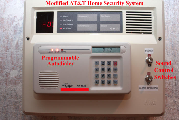
I have now successfully modified my AT&T Home Security System such that at a system event or zone trigger (fire, tamper, interior, etc), besides sounding the normal loud alarm, it automatically dials multiple telephone numbers, one after the other (my cell phone number is first on the list) and plays back a pre-recorded message I defined. I no longer use a monitoring company.
Overview of how my modified system works:
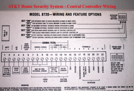
- When an system event (channel or zone), occurs, inside the CC, it raises the voltage on the applicable "channel" (also called zone) terminal to +12 volts direct current (VDC) (terminals 15 through 22) and it remains at 12VDC until the CC is cleared.
.jpg)
- When any zone goes to +12VDC, a "one-shot" circuit board opens up a normally closed (NC) line to my phone dialer, forcing it to begin to dial all phone numbers I have programmed into it. After one second, the one-shot closes the (NC) circuit to the autodialer and waits for another zone event. The one-shot board is required because the CC raises a zone voltage and keeps it there and if a simple relay was used to control the autodialer NC circuit, the autodialer would continue to cycle through all its stored phone numbers over and over again until the zone event is cleared. Obviously not desired operation.
- Once all phone numbers have been dialed, the autodialer shuts down and waits for another "trigger."
- Both the one-shot circuit board and the autodialer are powered by the CC. Neither is a significant current drain and should not diminish the time the CC can continue to operate simply on battery power.
How to modify the AT&T security system for a user programmer auto dialer:
- Open the central controller.
- Disconnect the backup battery (remove red terminal to battery)
- Unplug the CC power adapter.
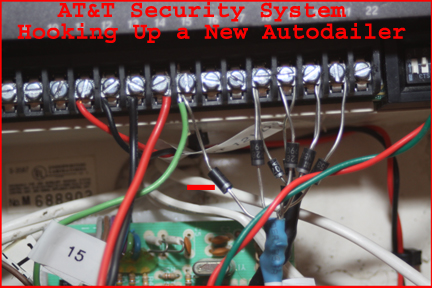
- Locate and remove the AT&T Digital Communicator from the Central Controller (CC). This means to unhook all wires connected to terminals 15 through 22 as well as the autodialer wires connected to terminals 11 and 12.
.jpg)
Note: picture above is my particular AT&T system and show digital enunciator (verbal announcements at alerts instead of siren) as well as AT&T autodialer.
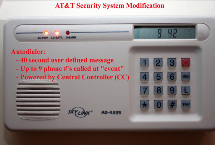
- Procure a Skylink AD44S automatic phone dialer or similar. I am sure there are several different manufacturer's auto dialers that would work. I like the quality of the Skylink and it has a built in NC circuit that I used with my one-shot board to trigger the autodialer at any CC zone event. I also like that it is constantly "armed."
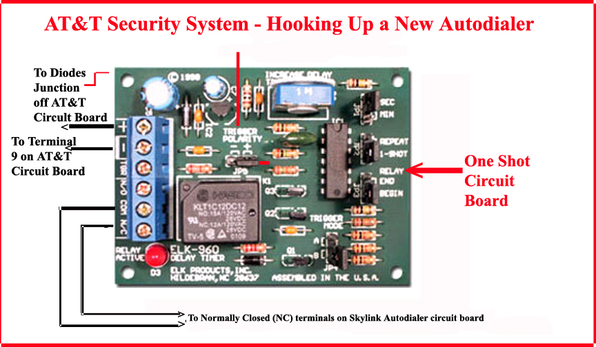
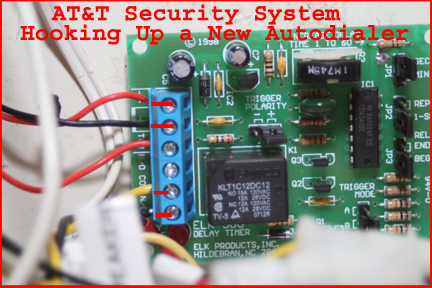
- Procure a small "one-shot" circuit board (I used an ELK-960.). When voltage is applied to the "trigger" of this board, it creates a single "pulse", which in my case, was to open the NC circuit of the autodialer for one second.
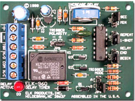
Note: one-shot circuit board comes with instructions for use and has jumper settings you might need to change depending on your specific setup.
- Procure diodes from Radio Shack.
- On the front cover of the CC, I mount the Skylink automatic phone dialer.
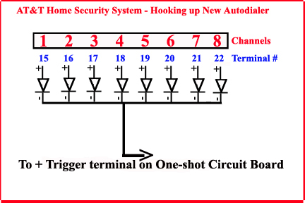
- Using diodes, I connect a diode to each of the "zones" on the CC and then twisted the diodes together, attached a wire and routed this wire to the trigger of the one-shot circuit board. I want several zones to trigger my autodialer but I could not simply connect the autodialer, actually the one-shot board, via wire to each zone as at a trigger of one zone, 12VDC, would be input into the output terminals of another zone. By using diodes, 12VDC supplied by one zone is not fed into any other zone terminal. Diodes only flow current in one direction and in my case, only towards my one-shot circuit board
Note: in my case, I did not actually connect a diode to terminal 22 or the "Trouble" Channel or zone as no desire to get an alert remotely because of a "no check-in" or low battery.
Note: the diodes I used have a silver bar mark at the "negative" end.
Note: one-shot circuit board comes with instructions.
Note: there are several "jumpers" on the board. Check their settings.
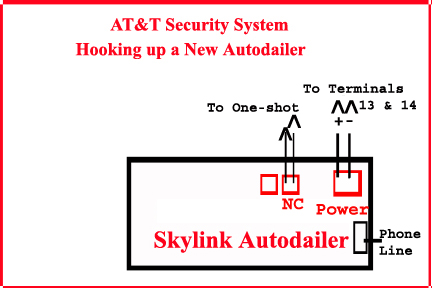
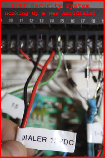
Note: the Skylink autodialer comes with a power line adapter but because 12VDC is available off the AT&T circuit board, I connected the Skylink to terminals 13 and 14.
Note: the blue boxes above are for connection to normally open and normally closed contacts.
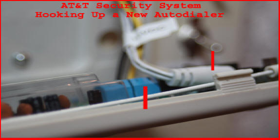
- Because I wanted to be able to remove the CC's front cover to replace the large backup battery when needed, I did not wire anything directly between the CC and the autodialer. Instead I used normal old computer power connectors, cutting as needed and soldering additional wire on and then using heat shrink tubing over the soldered junction. I then labeled all connectors. I have a connector for: dialer DC power: dialer NC; telephone line; and for my added CC sound control switches.
- Reconnect the CC battery and reconnect the CC's power adapter and then program the autodialer with my message and the telephone numbers I wished the dialer to call at a system event.
.
Skylink AD433s User Manual.PDF
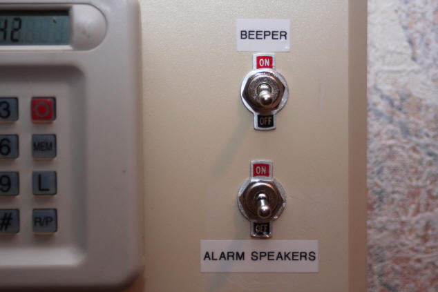
AT&T central controller (CC) sound control switches
When contemplating the modification of my AT&T CC for a user programmable autodialer, it occurred to me I should do something about the sounds coming from the AT&T CC.
Why?
- My wife has never understood the system or how to use a wireless keypad to silence either CC "trouble" chirps or the loud system alarm at burnt toast or other false alarm. Switches on both alarm speakers (siren) and CC chirp would make it easy for her to silence the system until I am home to properly deal with the situation.
- The CC's trouble chirp always seems to go off in the middle of the night and thus up out of bed, determine which device is not checking in, replace the battery in the offending device and reset the CC. A switch on the CC chirp solves this problem.
- Have never understood why the CC has to chirp at me, even at a reduced volume, when I opening up devices to replace batteries. I know the device is open cause I opened it and although at reduced volume, the CC's beeper or chirper drives our resident dog crazy. With a simple switch, I can turn off the CC buzzer whenever I change sensor batteries.
Switch on CC alarm
This is an easy switch to install. Simply one of the 2 wires to alarm speakers is routed to the center of a single throw switch mounted on the CC's front panel and the other wire of the switch routed to the sound board or siren terminal.
Switch on the CC's chirper
Getting a switch on the CC's chirper is not an easy task. The CC's chirper is a piezo, 3 pin, device mounted on the main circuit board of the CC. First you have to get the main circuit board loose from the CC's plastic frame box and then remove the black plastic cover over the CC's main circuit board. Then, you must unsolder the 3 pins going to the piezo chirper. To do this you will have to have a soldering iron and what is known as a solder sucker. A solder sucker is spring loaded and when solder begins to flow at a circuit board junction, the solder sucker is placed over the junction and its trigger pushed causing liquid solder to be pulled up into it. With solder removed from the 3 pins of the chirper, it can be gently removed from the circuit board. Now the 3 pins of the piezo chirper are labeled "G", "M" and "F". 3 pins are used so 2 volumes of chirp can be generated. In my case, I determined that the "G" pin was the return side of the device and thus if a switch was placed between this pin and the CC's circuit board, I could turn "off" or "on" the chirper.
Unfortunately, the piezo device has black plastic on each of the 3 pins extending down from the device right to the circuit board (I am sure to provide some mechanical strength) and thus, I had to break away some plastic on the G pin to expose enough pin to allow me to solder a wire to it. Now these pins are very small in diameter and some how, I managed to break the pin off from the device but could still see the metal of the G pin extending down into the device. So I soldered a small, thin, wire to the G pin and then place electric tape over the soldered connection. I then soldered a wire to the circuit board at the G junction. I then carefully connected the ribbon cable between the black plastic cover over the main board and routed my chirper wires through the bottom most grill work grill in the CC's plastic cover. I then snapped the circuit board into the black plastic CC cover and then snapped the entire assembly back into the frame of the CC.

I then placed a connector on the 2 wires coming from the main circuit board and soldered 2 wires and a an opposite sex connector to a switch I mounted on the front of the CC.
Listening in on My Home.
Ok, the AT&T system calls my cell phone at any system event but I still do not know what zone type triggered. To solve this problem, if not only partially, I procured a Magic Jack (Best Buy) and a USB-based microphone.
The Magic Jack is a USB plug-in device that once plugged into a USB port on any broadband Internet equipped computer provides a voice over Internet (VOIP) phone line (and yes, it really works or it works fine for me).

Once Magic Jack software was installed and I confirmed I had dial tone, I plugged into the same computer that is hosting Magic Jack, a USB microphone.
Once Windows recognized the microphone and loaded applicable drivers, I used the Magic Jack console displayed on my Windows screen and changed from a telephone device to a headset. Then from a drop down menu in Magic Jack, I selected my USB microphone as the headset microphone device.
Now because I wanted Magic Jack to auto answer at every incoming phone call, I had to edit one Window's registry entry for Magic Jack.
Run regedit
HKEY_CURRENT_USER\Software\talk4free\USB Softphone\Options\Calling Options\AutoAcceptCalls
change value from 0 to 1 and close regedit.
I then rebooted the system, to have the changed registry read at Magic Jack software startup.
Now upon an AT&T system event, once I have received notice on my cell phone, I dial the number of the Magic Jack (provided by Magic Jack) and listen in on what is going on inside my house. As my AT&T system has a voice announcer, I should hear either "Fire" or "Burglary" and thus know which local service I should call, either the fire department or the police.
Finally, to make sure this listen-in aspect of my modified AT&T security system works 24/7, the computer hosting the Magic Jack, the cable modem and router are all powered "on" 24/7 and are all connected to a uninterruptible power supply (UPS).
Click here for more AT&T Home Security System.