Shared Knowledge
"Hydronic Heating System - Control System"
26 October 2010
The control system of a hydronic heating system is not overly
complex and usually operates year in and year out without problems.
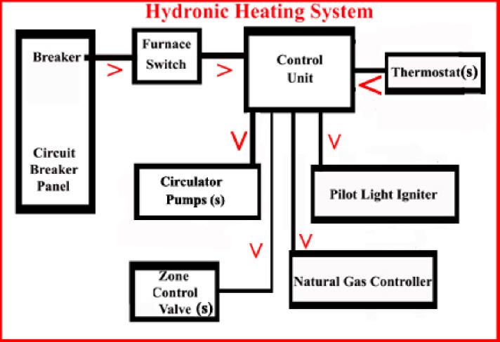
Below describes the components of the control system and their function.
After component descriptions, a narrative of normal system operation is provided.
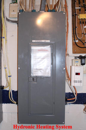
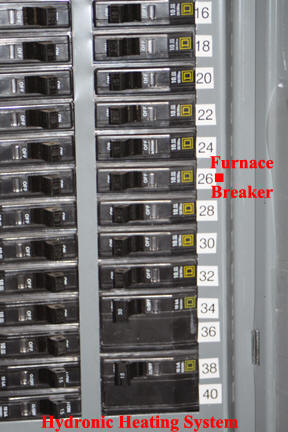
- Breaker in the circuit breaker panel. If wired correctly, the hydronic heating system should have its own, dedicated, circuit breaker in the house circuit breaker panel. If your system does not come on when you start it up for the first time, check the circuit breaker panel breaker.
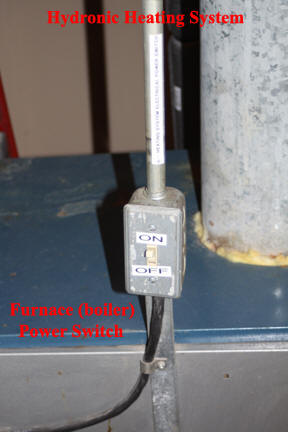
- Power switch right at furnace. Again, if wired correctly, there is a normal electrical switch mounted on or near the furnace that allows you to turn off the furnace completely in the spring or whenever maintenance is required.
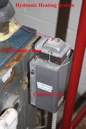
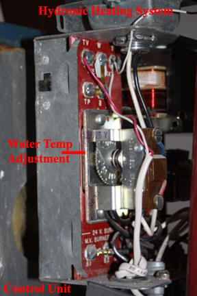
- Control unit. The main system control component is the control unit. This is normally mounted on the furnace itself but can be on the wall. If wall mounted, usually a line goes to the furnace to capture water temperature. The control unit responds to the thermostat(s) and causes pump(s) to run, zone control valve(s) to open, energizes the pilot light igniter and controls the fuel sources, such as natural gas. Control units are fairly sturdy beasts consisting of very little actual electronics but having several relays. Mounted on the control unit is a transformer. The transformer converts house power to 24 volts, which is used by the thermostat(s). Although sturdy beasts, control units can eventual suffer from a failed transformer or one or more relays failing to operate properly. Please note that the control unit does monitor system water temperature BUT NOT PRESSURE.
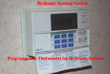
- Thermostat(s). In a single floor, single zone, home, only one thermostat will be present. In a multi-floor home, it is more normal to have one thermostat per floor. Thermostats for hydronic hearing systems either must be of the old round type that has a mercury switch inside or a more modern programmable thermostat that is made for hydronic heating systems. If a house has multiple zones and thus zone control valves, these valves draw a lot a current that the thermostat must switch and hold. A older round type with a mercury switch inside has no problem as zone control valve current flows through the mercury switch. However, in the more modern programmable thermostat, there must be a small relay inside that actually switches zone control valve voltage. Just to expand, a relay is a device that allows a very small amount of current to control a mechanical set of contacts what can switch and hold a much higher current flow. Thermostats do go bad, so if no heat and all else checks out, do not assume thermostat is fully functional.
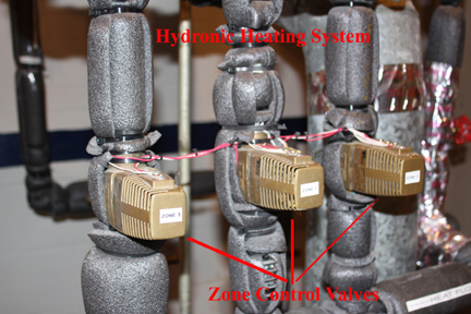
- Zone control valves. A single zone system will not have a zone control valve but a multi-floor, multi-thermostat system will. A zone control valve is an electrically operated valve that either denies or allows water to pass through it. If a floor does not need heat, the zone control valve for that floor will be closed. If a thermostat demands heat, the control unit will command the applicable zone control valve to open. Zone control valves are study devices but can and do fail.
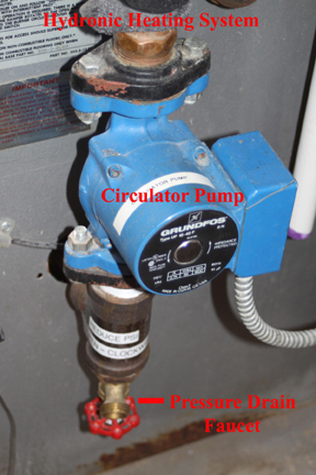
- Circulator pump(s). Most hydronic systems have only one circulator pump but I have seen older installations that have one pump per zone.
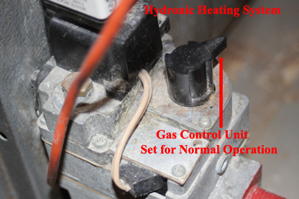
- Natural gas control unit. On a natural gas fired hyrdonic system, natural gas is routed to a special control unit. This unit performs the following functions: (1) when commanded by the main controller, allows a small amount of natural gas to flow to the pilot light opening, (2) Via a temperature probe inserted into the flame of the pilot light, waits until the temperature sensor reaches a set temperature before opening the main natural gas flow to the furnace. If the temperature sensor never reaches the defined, set, temperature, the main gas line is never opened to the furnace. Please note there that temperature probes do go bad or can be slightly moved out of the pilot light flame and this will cause the furnace to never heat.
- Pilot light igniter. When a thermostat demands heat, the controller will open the applicable zone valve and start the circulator pump. As water temperature in the system drops, at a set point, the controller will command the gas control valve to supply gas to the pilot light and then energize the pilot light spark unit. The spark unit sets at the opening of the pilot light inside the furnace. Once again, if your furnace does not heat, make sure the pilot light igniter is sparking.
