Shared Knowledge
"How to: Assemble a Desktop PC from Components"
12 November 2009
Summary: assembling a personal computer (PC) desktop from components is not difficult but does require some basic knowledge about: power supplies; various connectors and hard drive interfaces. Only a handful of tools are needed.
Background:
Everyone does something for the very first time and so if you have been thinking about "building" your own PC, what I provide below will hopefully help you.
I prefer to assembly desktops from components because the market for off-the-shelf, retail, systems is so competitive, manufacturers save a nickel where ever they can and thus off-the-shelf systems tend to be short on power supply watts, space for additional hard drives or other devices.
Assembly a PC desktop from components:
Note: before you procure components make sure they will support the operating system you intend to run. Mostly this has to do with video board specifications but also make sure you have enough random access memory (RAM) and hard disk drive space.
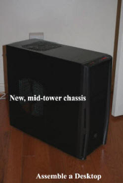
For this desktop went with a Thermaltake Series T, full, mid-tower because: it was on sale ($40); was designed with cooling in mind; has enough room inside for expansion and does not cramp my hands installing cables or drives.
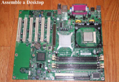
Motherboard: this is an older Intel with dual core 3.2GHZ. Lots of motherboard manufacturers but who knows Intel CPU's better than Intel? And this motherboard has/supports: AGP; 4GB of Ram; (2) IDE channels and (2) SATA ports; PCI slots and has on-board Ethernet, video and audio and can be had for about $70 off eBay. Note: be careful handling a motherboard. There are many capacitors (cylinders) sticking up off the board and you do not want to bend or break any of these off the board.)
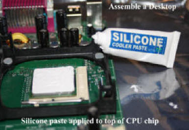
Motherboard came with CPU cooler installed but knew thermal paste between top of CPU chip and bottom of cooler was most likely dried and thus not providing any real thermal transfer, so removed cooling fan, cleaned CPU top of old paste and bottom of cooler and installed new thermal paste on top of CPU chip.
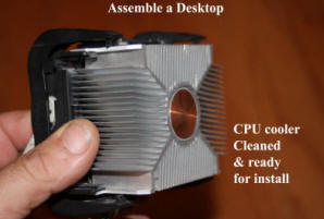
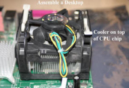
CPU cooler installation. Be careful and never force cooler into place. If you meet too much resistance trying to "latch" cooler in place, probably not mounted correctly to motherboard. CPU coolers vary depending up on the CPU and motherboard. Yours may not look exactly like what is shown above.
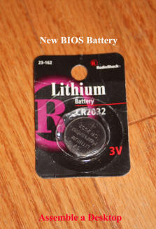
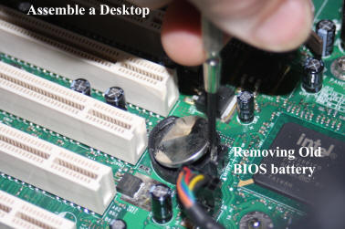
BIOS battery. BIOS (Basis Input Output System) settings (date, time, hard drives attached, boot order, etc.) stored on the motherboard must have a battery. Whether you buy a new or used motherboard, start off with a new BIOS battery.
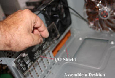
Motherboard connectors along the back edge of the board fit through what is called I/O Shield. Although there has been some standardization of motherboard connectors, make sure you get an I/O shield for your specific motherboard. .
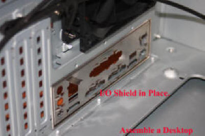
There are no screws associated with the I/O Shield. It simply snaps into the hole in the chassis. As the I/O Shield is made out of very thin material, make sure you do not bend it out of shape installing it and make sure you install it in the right orientation so the motherboard connectors will actually fit through when the motherboard is mounted in the chassis.

Motherboard standoffs. Obviously the motherboard can not sit flush on the metal of the chassis, case. (Talk about electrical short). Looking at the motherboard, you will see holes along the edge where mounting screws are supposed to go as well as a hole or 2 in the middle of the board (the middle of the board must be supported too.) Looking at my motherboard (an ATX form factor motherboard) and the chassis, I noticed the chassis was marked as to where the motherboard must be attached. In my case, multiple points are simply raised portions of the case backside, while other holes require the installation of a standoffs. (Provided with new case.) To make sure all standoffs I had to install were down tight and would not move, I used a nut driver.

With motherboard standoffs in place, I placed the motherboard into the chassis and fitted the motherboard connectors through the I/O shield. Checking that all connectors where fully exposed through the I/O Shield, I used machine screws that came with the chassis to mount the motherboard in place. I used a screw at each and every motherboard mount hole.

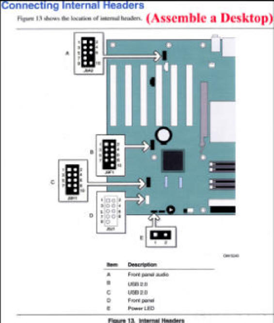
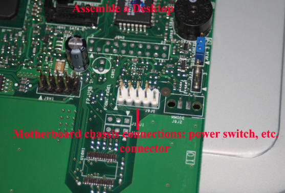
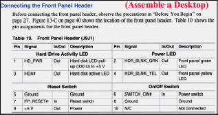
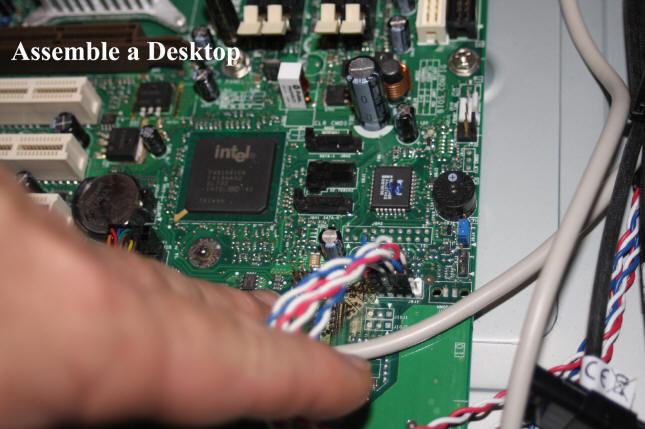
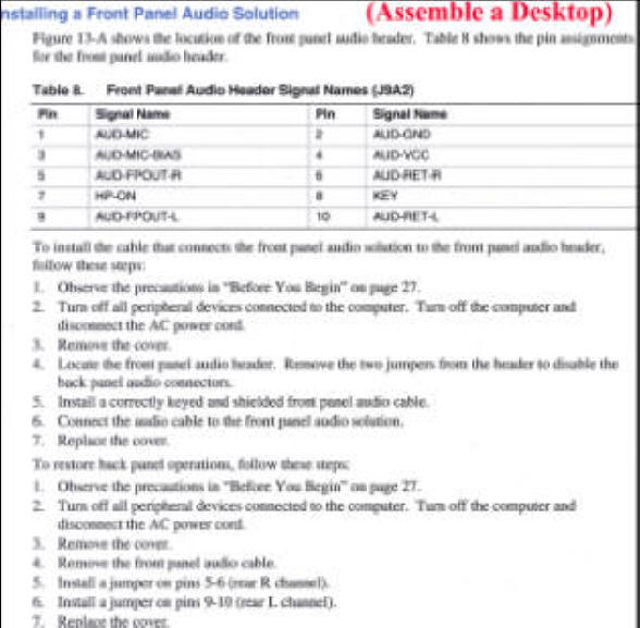
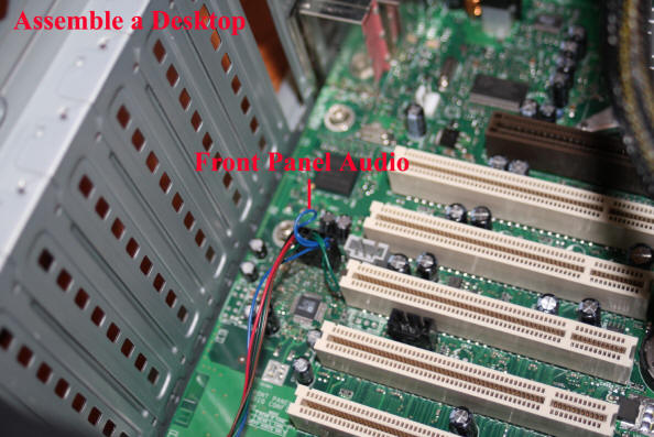
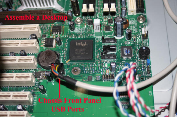
Motherboard connections. With the motherboard installed in the chassis, time to connect various to the motherboard: power on/off switch, reset switch, power light, front panel audio and front panel USB ports. To determine where to connect various chassis cables I consulted the product guide for my motherboard.

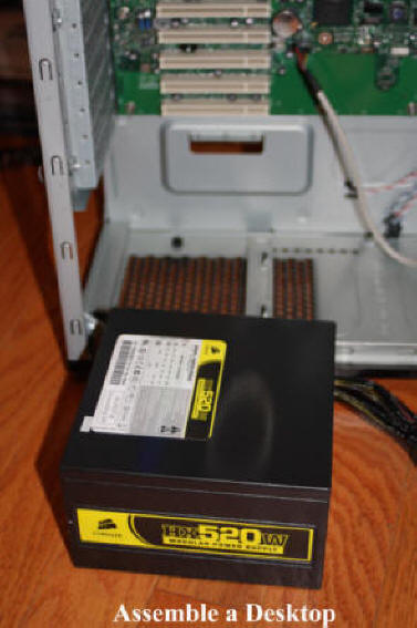
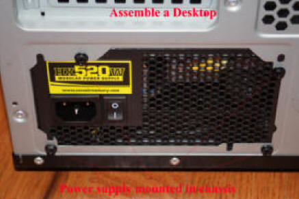
Power Supply. There is nothing more important to the health of all PC components that proper cooling and the power supply. Again, because of the highly competitive market, off-the-shelf systems tend to have very, very, small power supplies. No, power supplies do not fail all that much but with a underpowered (watts) power supply, what should be +5 volts can become +4.5 or even less. I just do not skimp on the power supply. Also, I like modular power supplies as they keep the number of power cables in the chassis to a minimum, reducing clutter and not interfering with chassis air flow for cooling.
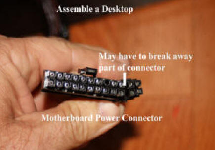
Power supplies are designed to work with most, if not all, motherboards and thus all that is provided in the way of motherboard connectors by the power supply may not be required for a specific motherboard. In my case, I had to break off (connector had a break point) part of the main motherboard connector to get the power supply connector to fit onto the motherboard.
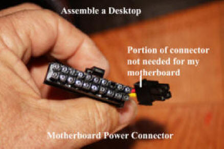
The power supply connector that goes into the motherboard is keyed. It will only fit one way. Make sure it latches firmly into place.
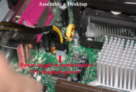
Besides the main motherboard power connector, my motherboard requires a separate power supply connector specifically for the CPU. If you buy a power supply make sure it has the correct connector required of the motherboard/CPU chip combination you are using.
.jpg)
.jpg)
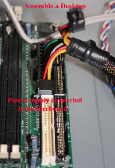
Chassis cabling. Above 2 images shows care I take to keep all motherboard related cables bundled and out of the way, ensuring no blockage of air flow. Loose cables, wires, can be easily pulled, disconnected or even shorted while working inside the chassis. I use cable ties, a lot.
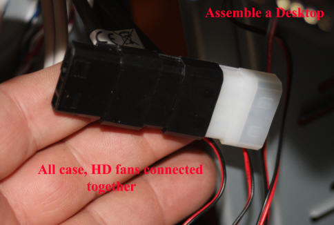
Fan power supply cabling. My mid-tower chassis came with 2 built-in fans and below you will see that I always use hard drive coolers and then I connect all fan power connectors together and then power them all by one cable from my modular power supply.
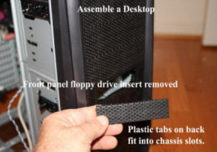
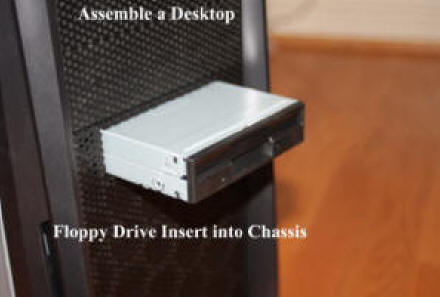
To insert any device like a floppy drive into an "external" bay, you have to remove a bay cover. For me, I had to place my hand in behind the cover and press outward on 2 tabs on the far end of the cover and then push the cover back into the case for removal. What you have to do to remove an "external" bay cover will depend on your chassis/case but most are similar to what I just described.
.jpg)
.jpg)

Memory. For any specific memory requirement (this motherboard needed DDR400), there is a wide variety of different manufacturers and associated costs. I don't skimp on memory. In this case, I needed a matching pair for my hyperthreading motherboard and went with the top of the line with attached heat sinks.
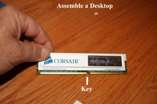
Memory modules have a key in the edge connector. Match up the key in the module with the memory slots in your motherboard.
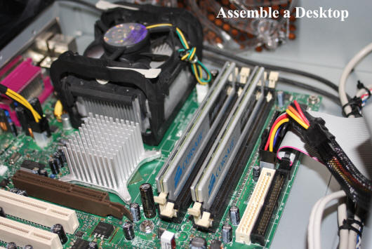
Memory module insertion into motherboard slots. How memory modules are inserted into motherboard slots depends upon the motherboard. In my situation, I wanted hyperthreading memory management and thus had to split my 2GB of memory across the 4 slots as shown. Consult your motherboard manual for details.
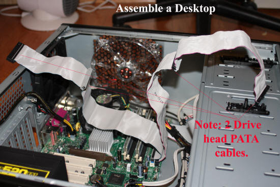
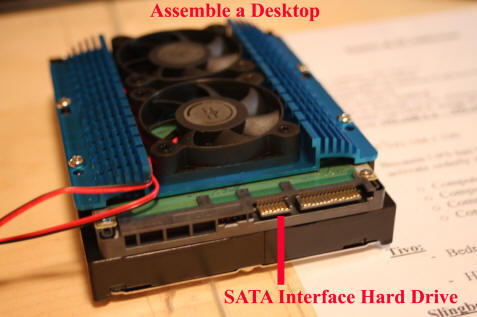
Hard drives and CD-DVD reader/burner. Because I had a 320GB PATA hard drive and the motherboard I was using supported (2) IDE channels and (2) SATA ports, I decided to use my 320GB drive as "C:" and put it on 1 IDE channel and procure a PATA CD-DVD reader/burner and place it on the other IDE channel and finally, procure a 1.5TB SATA drive and place it on 1 of the 2 SATA motherboard ports. By configuring this way, it will be easy to add either PATA or SATA devices in the future.
Note that I used IDE cables with 2 drive "heads" on the 2 IDE channels. This allows easy add of additional PATA devices in the future. Note: when using a 2 headed IDE cable with only a single device, you must connect the device to the first drive head.

SATA cable connection. In this case, cable was connected to motherboard SATA port 0.
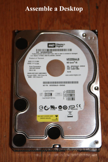
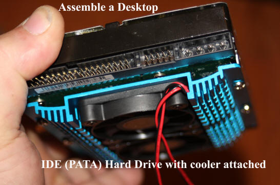
320GB PATA drive I had. Note that it is a 7200RPM drive. Slower and faster rotational speed drives are available. I go with the 7200RPM as readily available and faster than older 5400RPM drives and costs significantly less than 10,000RPM drives on market.
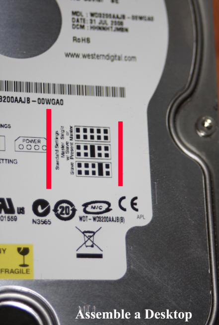
As it was my intent to use my 320GB hard drive on the motherboard's primary IDE channel without any other devices present on the channel, I had to ensure that the 320GB drive's "Master" "Slave" jumpers were set to "Master" or "Single Drive." All PATA drives have a jumper map either on top the drive or with included (new drive) documentation. "Jumper" in this situation means a small hunk of plastic with metal inside that goes across pins in a special section, area on the back edge of the drive.
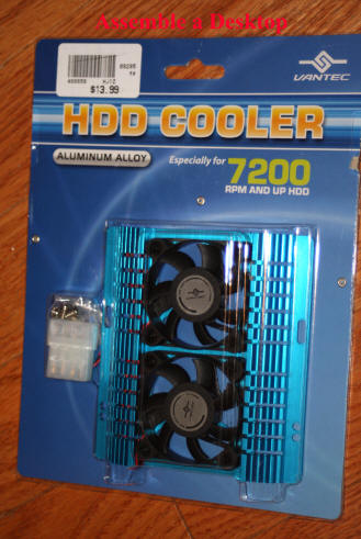
Hard drive coolers. Perhaps overkill, but I attach a hard drive cooler to each and every hard drive I install in a system. I have found that a cooler reduces drive temperatures by between 5 and 20 degrees. Again, heat is the enemy of any electronic device. Hard drive coolers are available in cost from very cheap to very expensive. I go with the blue, finned, unit above as it between cheap and expensive in cost ($12).
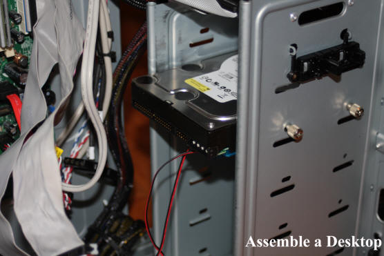
320GB hard drive mounted in chassis. Note: hard drive is mounted with plenty of space, i.e. air around it.
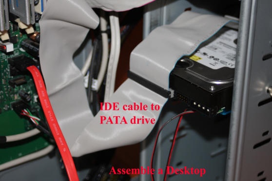
Primary IDE channel cable attached to 320GB "C:" drive. Note: the first drive head or connector must be used when only 1 drive or device present on a IDE channel.
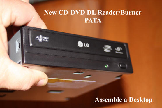
CD-DVD reader/burner. Available with either a PATA or SATA interface. I went with PATA as wanted to save second SATA port for another hard drive in the future and SATA speed not needed by CD-DVD reader/burner. As was the case with the 320GB hard drive, I had to set the "Master" "Slavc" jumper on this PATA device to "Master."
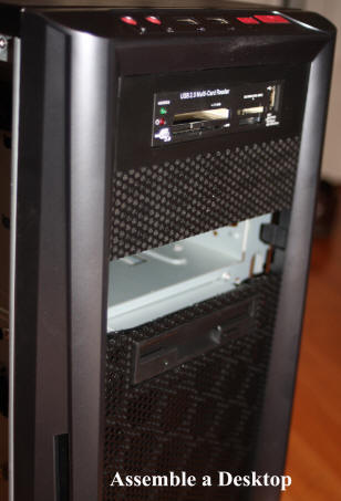
Removing bay cover to allow insertion of CD-DVD reader/burner. In most cases, a drive bay cover can be removed by placing your hand into the back of the bay and pinching tabs outward on both sides of the bay. To remove a drive bay cover from your specific chassis, consult chassis documentation. Drive bay covers can be hard to remove the first time, so go slowly. And keep those covers after you remove them. Covers are specific to a chassis and 2 or more years from now when you want to replace the cover, you might not be able to find a replacement anywhere.
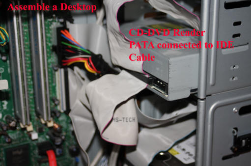
CD-DVD Reader/Burner is attached to secondary IDE channel as "Master" and only device on that channel. Once again note the CD-DVD reader/burner is attached to the first drive head on the IDE cable off motherboard channel 1.
As my data drive, I went with a 1.5TB, 7200RPM, SATA and once again, mounted a cooler onto it before installing in my system. As for size, with price per megabyte continuing to drop and the size of objects stored going up all the time, makes no sense to me to procure anything less than a very large drive. Why have to replace a drive in the future with a larger drive?
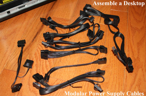
Time to power supply cable the system. As defined above, I procured a modular power supply, which allows me to add only those cables I need for the devices installed. In the image above, I show all the cables that came with my 520watt modular power supply.
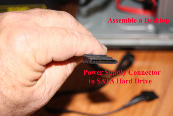
Up to the time of SATA, most device power connections used the same 4 pin connector. SATA is different and above shows the power connector needed for a SATA drive.

Note how all power cables are routed to not interfere with chassis, case, air flow.
.jpg)
This shows power supply cables attached to modular power supply. Note that I still have 2 cable connectors open for more power cables.
With all component installed other than USB card reader, time to install an operating system on 320GB "C:" drive. To do this: one last check of all connections inside chassis to make sure everything cabled properly; monitor, mouse and keyboard attached and then power cord inserted into power supply on back of chassis and power switch there flipped to "on." At this point, system began to come alive with fans turning for a second for 2 and then the system went quiet. I then pressed the power button on the front panel of the chassis.
At this point, the motherboard came alive and by striking Function Key 2 (depends on your motherboard) I forced the system into BIOS settings. The screen below is the very first BIOS screen displayed.
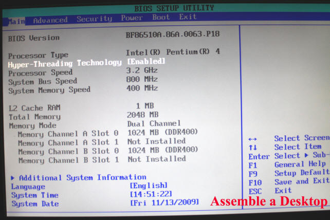
This BIOS first screen verifies that the motherboard is alive and shows the date/time and amount of memory installed. As I replaced the BIOS battery before installing the motherboard into the chassis, my BIOS came up and reported a Checksum error. This means nothing other than I had to set time and date again and check other settings like state of Numlock key, etc. Note: what your motherboard displays at its first BIOS screen may not match exactly what is shown above.
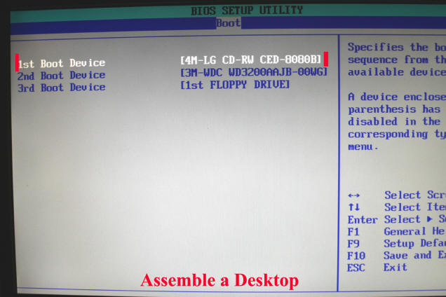
Now because I wanted the system to boot from WinXP install disc, went to boot part of BIOS and set first boot device to CD-DVD reader/burner. I then opened the tray on the CD-DVD Reader/Burner and inserted the WinXP install disc and closed the tray.
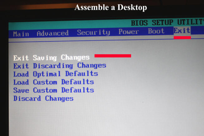
With boot priority set to CD-DVD Reader/Burner, went to Exit menu item and selected "Exit Saving Changes." System rebooted into Windows XP install disc. Followed instructions on screen from WinXP and installed making sure that my 320GB drive was the intended target for the OS. Now since my motherboard has onboard audio, Ethernet and video, I had to install drivers for these specific devices as well as other motherboard function before continuing. Once I had installed all motherboard specific drivers, I attached an router connected Ethernet cable to my motherboard and confirmed I had Internet. I then activated Windows XP over the Internet. Once WinXP was activated, I installed Service Pack 3, which I had on disc and then proceeded to download all necessary updates to WinXP from Microsoft's update website.
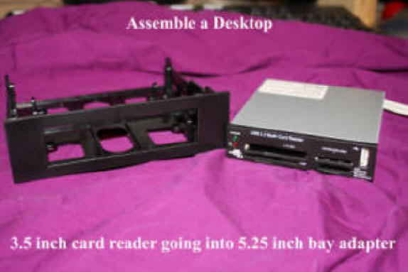
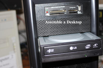
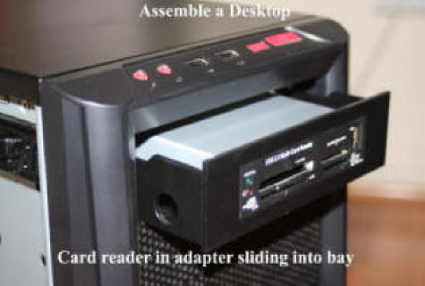
Who does not have a digital camera these days or use a thumb drive? So, I procured and installed a "universal" memory reader like shown above. As this device only seems to come in a 3.5inch form factor, I had to procure an external bay adapter and install reader in adapter before mounting in my chassis.
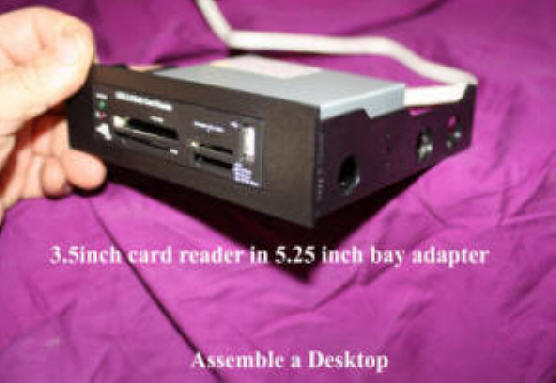
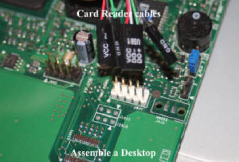
With system powered off, I consulted the motherboard USB connector map and connected the cable from the universal memory card reader. At system power on, the memory slots in the reader were recognized as new drives. Note: I actually installed the memory card reader before I installed WinXP and found that I was sloppy when installing and Windows decided to name my 320GB drive "H:" instead of "C:", seeing the memory card reader "drives" first. As there was no way to change the drive letter of the OS drive, had to format my 320GB drive, unhook the USB card reader cable from the motherboard and install WinXP again. :(
With USB memory card reader installed and functioning, I all done. To be added in the near term is AGP video board with 512MB of onboard memory to allow gaming and another pair of memory modules to expand system to 4GB total of memory.

So that is it. Not a hard task assembling a desktop PC from components but lots of little steps and mechanic and electric work to be done. Assembling from components is not for everyone but it is a kick the first time you power up all that dead technology and get BIOS to show that all is well.