“HP Pavilion
N5000 Series - Disassembly”
Updated 5 May 2006
Updated 20 October 2006
Updated 2 April 2007
Over the past several years, I have had cause to go inside
a Hewlett Packard (HP) Pavilion N5190 laptop several times and decided this
last time to document disassembly via digital images and text
descriptions. Of course to keep this document relatively small in size, I have
not taken an image of every single step involved and images are of relatively
poor quality but I hope the following is some use to you.
For
the most part, I have had to go inside a N5190 when the system starts shutting
down on its own, at random. From my experience, this is a cooling problem and
requires the system be opened up and either the fan on the CPU be replaced or
cleared of dust and dirt but at a minimum the fan removed and remounted to the
CPU using thermal conductive paste. Thermal conductive paste is available at
Radio Shack and at computer stores. (Note that I have come across machines where
the problem is not with the cpu or fan or any other user replaceable part. The
system will start up fine but after an hour or so, the cpu just stops
running. In this case, I have concluded, after swapping out everything I could,
that some component on the motherboard had gone bad and junked the motherboard.) The other reason I have had to go into the
N5190 is to replace or upgrade the hard drive.
Disassembly
of any device does require a decent visual memory as there is no way I can
document every screw or everywhere some tab of one piece must fit into
another before everything will come together properly. The point being is that
if you are going into anything, go slowly, observing how parts fit together and
where screws are located and not located. Additionally, if something does not
want to be removed then most likely you have overlooked a screw or a metal tab
somewhere. If something is hard to get out, do not force it, back away and look
for what is holding the part from moving. In the case of plastic case pieces,
yes, these snap together and have to be pried part carefully but if you meet
resistance, back away for a while and check everything over again.
In
the case of the N5190, all screws are the same diameter, for the most part, but of different
lengths. If one does not tighten up, or gets hard to tighten up, then perhaps
you are using a wrong length screw.
Finally, because the entire HP
N5000 series appears to use the same case and component layout internally, this
document probably pertains to the entire N5000 series laptops.
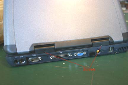
Turn off the computer, unplug the power
adapter, and
remove battery. Close LCD lid all the way. On back of computer, remove the 2 hinge
screws.
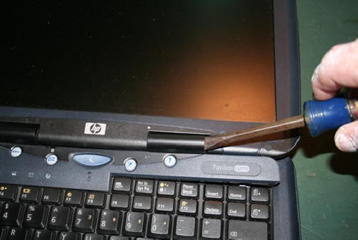
Open
LCD and using a flat blade screwdriver, pry up the plastic switch board cover
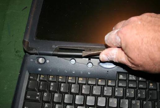
at the far right where the switch board cover covers the right LCD hinge. This cover snaps over the hinges so be careful prying it up. Once loose
on the right, use screwdriver to pry up on left hinge and when loose, remove
switch board cover. Other than the 2 screws on the back of the laptop
at the hinges, there are no other screws holding the switch board cover in
place. I simply snaps into and out of place. I have removed many of these
and never broken a one, so just get the cover to start coming upward and
then it will be easy.
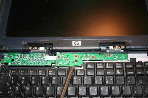
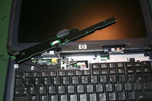
With
switch board cover out of the way, remove screws holding the switch board in place
(one on the far left and one about dead center).
Note that the switch board has a connector on the backside, which is pushed
into a connector on the motherboard so, you will have to pry up the board
slowly from the middle of the board. Also note that the switch board’s far right
end actually sits under a metal tab in the right metal frame of the laptop.
Once you have the switch board out of the laptop, the switch board will still be
connected to the LCD by a multi-wire cable. This cable connects the laptop's
video driver board to the LCD. Slowly lift the video cable out of the
connector on the video board and when the switchboard is completely free,
just lay it on top of the LCD to get it out of the way.
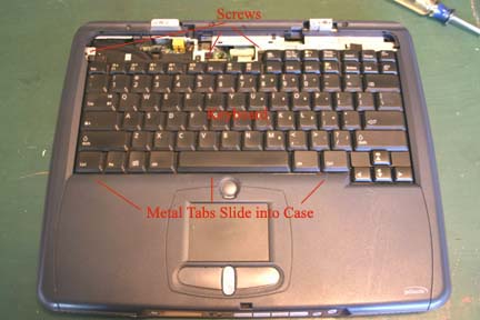
With the switch board out of the way,
unscrew the screws holding the keyboard down. Some screws might not actually
come out of the metal of the keyboard and that is ok as long as they are no
longer screwed into the metal frame of the laptop. Once you have these screws out or loose, lift
up on the front of the keyboard and then pull it out towards the LCD screen.
The back of the keyboard is only held in place by metal tabs which fit into
tab slots in the plastic laptop top. With the keyboard up out of the laptop,
it will still be connected to the motherboard by a ribbon type cable on the
left side of the keyboard. You do not have to remove this cable if you are
only going to replace a hard drive, cpu fan or cpu. Note here that the
keyboard connector fits over top the motherboard connector. The ribbon cable
and connector coming from the keyboard are one piece. When you reassemble,
get the keyboard connector installed before you reinsert the keyboard rear
metal tabs into the plastic top and then screw down all screws holding the
keyboard in place. Finally, make sure the keyboard connector is pushed all
the way down on the motherboard connector or you may have keyboard problems
later.
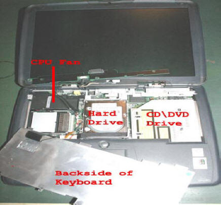
With the keyboard out of the way,
you can now get to the hard drive, the cpu fan and the cpu.
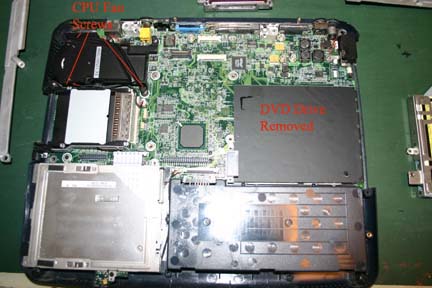
To remove the cpu
fan, which is the black device in the extreme left upper corner of
the laptop, unscrew the 4 screws holding it down to the motherboard. These 4
screws have a metal spring between the top of the screw and a nut type metal
standoff on the bottom. Once you have all screws loose, unhook the cable
which comes from the fan and connects to the motherboard. Now gently lift up
on the back (closest to hard drive) of the fan and if all screws are loose, you will be able to work
the fan out away from the cpu, which is underneath it. If you know the fan
actually works and does not need replacing, I suggest you do at least the
following: (1) using a can of compressed air, blow all the dust out of the
cooling fins, (2) where the fan makes contact with the cpu, clean off all
black paint. HP made a serious mistake in not cleaning off black paint from
the bottom of the fan and not using heat conductive paste between the fan
and the cpu and (3) Apply a generous amount of heat conductive paste to the
fan heat sink and then replace the fan into the laptop and screw it down via
the 4 screws.
If you are
replacing the cpu, after the cooling fan is removed, insert a flat
blade screw driver into the cpu socket latch and turn the screw driver
counter clockwise. When you do this, you will see the cpu chip move slightly
back away from the latch. Now lift out the cpu. Insert the new cpu such that
the pins align with the socket and again insert flat blade screw driver into
the socket latch and this time rotate the driver clockwise to have the chip
move towards the latch and lock into place.
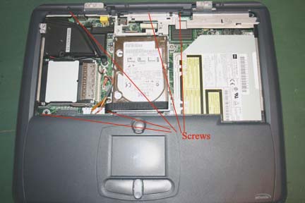
If you are replacing the hard drive, unscrew
the 4 screws holding the hard drive caddy to the motherboard. Before you lift the caddy out of the laptop, note how the caddy fits over top of
the metal rails in the back. You will need to remember this when you replace
the hard drive caddy. With all caddy screws loose, use a flat blade screw driver
to gently pull on on the cloth handle on the front of the hard drive until
the left side of the cloth lift handle releases from its Velcro home. With
the cloth up high enough to get your fingers under it, lift straight up and
the hard drive should lift right out of the laptop. If the caddy does not
want to lift out, check that all 4 screws have been removed. With the hard
drive caddy out of the laptop, you will now have to remove the connector on
the front of the drive which converts the horizontal pins of the drive to
vertical pins which plug into the motherboard. This connector is plastic and
cheap and easily broken, so be careful. This connector has two tits on it
which help you align the connector into the motherboard connector and can be
used to gently remove the connector. Push gently on one side and see the
connector move off the hard drive pins a little and then switch to the other
tit and push and see the connector move off the hard drive pins. Continue
back and forth until the connector comes off. Now turn the caddy over and
remove the 4 screws which hold the hard drive to the caddy. Take new drive
and place into caddy and mount using the 4 screws. Now gently replace the
horizontal to vertical pins connector. Place caddy into laptop with the rear of
the caddy over top metal of laptop and caddy screw holes aligned with holes
in motherboard. With all aligned, drive caddy front connector should seat
itself but some slight pressure downwards might be required. Do not push on
connector if all screw holes in caddy are not perfectly aligned with holes
in motherboard and never push on the hard drive itself. Once hard drive caddy is in place, reattach it to
motherboard with 4 screws. Now using a flat blade screw driver, fold over
the cloth handle on the left side of the caddy such that the Velcro catches and the
excess cloth is taken up and does not get in the way when you replace the
keyboard.
CD\DVD Replacement. If you need to replace the
CD\DVD drive, unfortunately you will have to continue disassemble.
Although the only screw holding the CD\DVD drive in place is one of the 4
screws holding the hard drive caddy in place, simply removing the hard drive
caddy and then pushing the CD\DVD drive out of the case does not work. See
instructions below.
If you need to replace the CD\DVD
drive, video driver board, floppy drive or the BIOS battery, you will have to
continue disassembly.
If you have not already
done so, remove the LCD assembly from the laptop. This is done by removing
the 2 screws at each hinge and detaching the LCD connector from the
video board. It is hard to get to the actual connector here so gently pull
upwards on the cable until the connector comes free of the video board. Set
LCD assembly aside. Also remove the keyboard
completely and set it aside. Now turn the laptop over so you can see the
bottom and remove all screws, which attach the bottom shell to the top cover.
.jpg)
With both bottom and top screws
removed, starting at the rear right hand corner of the case, look at how the
bottom and top parts of the case fit together and using a flat blade screw
driver or your fingers begin to separate the top half cover from the bottom
cover.
Like the switch board cover, the top case half is snapped into the bottom
case half and you will have to apply some pressure to get the top to begin
to come loose from the bottom. Do not be alarmed if you hear a snapping
noise at first. You have not broken the top cover, it is just unsnapping
from the bottom cover. Once the cases have begun to separate, slowly
move around the case separating the 2 cases until the top is completely free
of the bottom half. Now lift the top half off the bottom half slowly and you
will see that there are several connectors you will have to unplug from the
motherboard to completely remove the top half. The worst of these 3 is the
touchpad connector which is a ribbon type. To unplug this cable from the
motherboard, you grasp the cable and pull straight out. Note that when you
reinstall the top cover, you will have to connect the touchpad connector
first and this can be a bear. The cable coming from the touchpad\top cover
is a true ribbon cable with no connector on the end. You have to align the
ribbon cable with the slot in the motherboard connector and push straight
down. A pair of needle nose piers is handy here. Make sure you have the
ribbon cable seated all the way down into the motherboard connector and
equally so on both sides of the cable. You will be able to tell by pushing
down on the ribbon cable when it has bottomed out into the motherboard
connector.
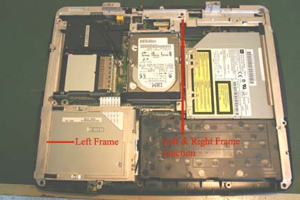
At this point, if your goal is to replace the
CD\DVD drive,
remove the hard drive caddy and then loosen the screw at the very front of
the right frame (closest to front of laptop). Now lift up slightly on
this frame and at the same time push the CD\DVD drive out of the laptop. To replace the CD\DVD drive, insert into the slot in the case,
lift up slightly on the right metal frame and
gently push the CD\DVD drive into the laptop. At some point you might meet resistance and if so, stop
and look where the drive is catching the case. In all likelihood, it is
hitting something on the right side of the drive and you might have to lift
up or push down the drive to get it to slide all the way into the case. Once
the drive is inserted, look on the side of the laptop where the drive is
located and make sure it is aligned properly with the case and the modem and
Ethernet connectors. If the drive has a space between it and the modem and
Ethernet connectors or appears to be not aligned with these connectors,
remove drive and try to insert it again. If you do not ensure proper
alignment of the CD\DVD drive, when you go to replace the top cover, it is
not going to want to snap over and near the CD\DVD drive.
If your goal is to replace the
floppy drive, loosen the metal rail on
the left side of the case and then all screws holding the floppy in place
and finally the ribbon cable. Now gently lift on the left metal frame and push
the floppy drive out of case.
To get to the Video Driver Board you will have to
remove the metal frames around the top of the case. Since the left metal frame
overlaps the right frame, remove the screws holding the left frame to the
laptop case bottom first. Then remove the screws holding the right metal frame
in place. Make sure to remove the screws on the back of the laptop where the
ports or connectors are located, which go into the metal frames. After both
frames are free of screws, lift up on the left frame and remove it. Once the
left is out of the way, remove the right frame.
Video Driver Board. The LCD
video driver board is what actually sends pixel information to the LCD display.
This removable board sets on the right side of the laptop near the rear. It
is held in place by 2 screws. Once you remove these screws you will have to
lift the board out of the laptop noting that it has 2 connectors on the
back side, which fit over connectors on the motherboard. If you are replacing
the video board, make note of the position of the dip switches on the
defective board as you are going to want to set the new video board to
the same dip switch setting. The dip switch settings are different depending
upon the manufacturer of the LCD used in your laptop. HP used many different
LCD suppliers and thus your dip switch settings could be different from whatever
the new or used video driver board defaults. Also note here that if you have
to ever swap out a complete LCD, you will need to know the LCD manufacturer
and be sure to set the video driver board dip switches for the new LCD.
To replace the BIOS battery, repair the
motherboard mounted power adapter input jack or replace the motherboard,
you will have to continue with disassembly.
If you have not already done so, remove hard
drive caddy, cpu fan, CD\DVD drive, floppy drive. Now remove all screws
holding the motherboard to the bottom case. Additional, remove all rear
connector, cable connection screws. These screws actually extend through a
metal plate on the back of the laptop. Once you think you have all screws
removed, begin to lift the motherboard at the upper right hand corner. It
should lift without a problem but if you meet resistance, look for a screw
you missed removing. Also note that when you lift up on the motherboard a
cable from the modem\Ethernet card may be taped to the bottom of the
motherboard. You will have to disconnect the cable from the motherboard up
near the power adapter jack and loosen the cable from the motherboard. When
you reinsert the motherboard, it does not matter how this cable runs
under the motherboard but make sure it does not stick out into the battery
compartment.
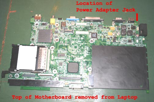
The power adapter jack. One of
the primary reasons for a completely dead laptop is that the power adapter
jack has broken and the laptop is not getting power. To check this, using a
voltmeter, first check that your power adapter is delivering 19 volts DC. If
the adapter is working, plug the adapter into the motherboard jack and turn
the motherboard over. Find the motherboard power adapter jack and if should
be pretty obvious where the jack actually makes electrical connections to
the board (right underneath the jack). Using a voltmeter, find out of the
motherboard is getting 19 volts DC. If not, the jack is broken and will have
to be replaced. I do not know a good source for these jacks. I have replaced
one using a good unit from a bum motherboard but know there must be a source
on the net somewhere. Radio shack does not carry this jack as far as I can
tell. To replace the jack you will need at least a 40 watt soldering iron
and what is known as a solder sucker (Radio Shack sells solder suckers). To
remove the old jack, obviously remove the power adapter input from the jack
and then heat one of the 2 power adapter jack terminals. Once the solder is
liquid, use the solder sucker to suck up all the solder. Repeat as necessary
until all solder around the terminal is gone. Now do the same thing to the
other power terminal. Finally, examine the power adapter jack and you will
see that it has a metal shroud around it which is also soldered to the
motherboard. Locate this terminal on the bottom of the motherboard and using
the solder sucker and soldering iron, clean this terminal. Once you have all
terminals clean or as clean as you can get them, use your fingers to begin
to wiggle the jack out of the motherboard. Back and forth, slowly should do
the trick. If the jack seems set pretty hard into the motherboard, check
that you have removed all solder around all terminals and remove more if
necessary. This jack will come out of the motherboard. Note that there are
other motherboard components near the power adapter jack and if you try to
use a screw driver to pry the jack out, you might damage one of the very
small flat pack resistors and then you are in trouble. Be careful in and
around the power adapter jack. Once you have a new jack, insert into holes
in motherboard and solder down. Once finished, attached power adapter to
jack and again check to see that motherboard now getting 19 volts.
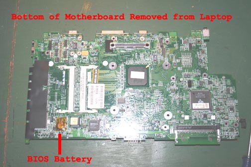
BIOS Battery. Read somewhere that HP did not
make the BIOS battery user replaceable as according to them, life of a
laptop is 7 years and BIOS battery is supposed to last 7 years. If you need
to replace BIOS battery, it is located on the bottom of the motherboard and
is a regular type "watch" battery but has been spot wielded to 2 tabs, which
are then soldered into motherboard. I personally have not replaced a BIOS
battery on this model but suspect there are at least 2 ways to do it. (1)
Unsolder battery from motherboard and determine voltage of battery by
looking on battery. Hopefully the spot wielded tabs do not cover the make
and model of the battery. Knowing the battery voltage, perhaps you can find
one that is covered in plastic and has wires on it to a connector of some
type for some other application, but if you clip the connector off, you
should be able to solder the new battery into place. Obvious you need to pay
attention as to positive and negative tabs and match what was in the laptop
to begin with. The second possibility is to remove the old BIOS battery and
take it to a Battery Store. Battery Stores are beginning to become
nation-wide and they have the ability to spot wield tabs onto any battery
they have and they will have a replacement for the old HP BIOS battery. Note
here that do not just buy a battery and try to solder the old tabs to it.
Soldering a battery is never recommended as they might explode from the
heat.
Of course, assembly is the reverse of what I have shown.
As with disassembly, go slowly and make sure you put back all screws in one
assembly before adding another. If you have to take one assembly back off to
make another fit properly so be it. Take pride in the fact that you doing it
yourself and once you have been inside, you will never have fear of it again.
Hope
this helps.
Of finally, don't have a N5190
you are dealing with? Try
http://repair4laptop.org