
Shared Knowledge
"Hydronic Heating System - Configuration and Components"
25 Oct 2010
Summary: at first glance, a home hydronic heating system can intimidating, all those pipes and valves, but once you understand each of the basic components, the system is not all that complicated. In this document, I provide information as the purpose of each hydronic system component and various system configurations.
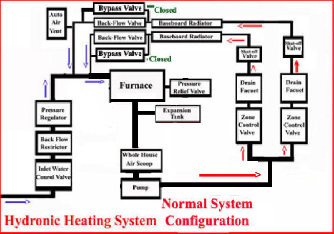
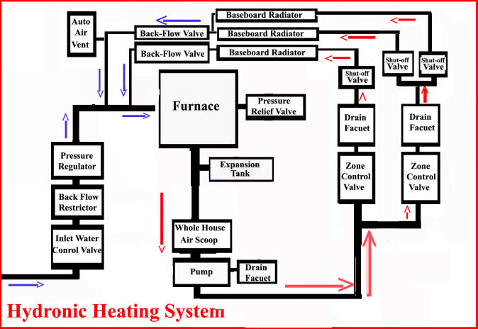
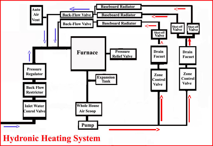
1. A single zone and loop system. This sort of configuration is normally found in a small, single story home. The blue and red arrows show normal movement of water through an operational system. Blue = cool water while red = furnace heated water.
The basic components of this configuration and all home hydronic heating system include:
- Inlet water control valve. Water gets into the hydronic heating system from house water through a inlet water control valve. Normally this valve is open allowing water to enter the system as needed but the valve can be closed when the system is to be drained or other operations requiring an empty system or zone are required.

- Back Flow Restrictor. A back flow restrictor on the water inlet line keeps hydronic heating system water from getting back into your house's water system. I.E. house water is only allowed to enter the system. Water in the heating system is never allowed to enter house water supply.
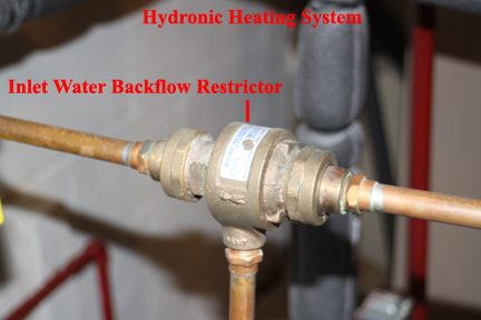
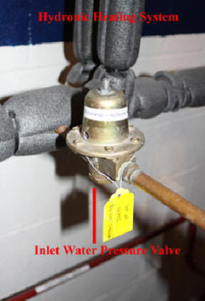
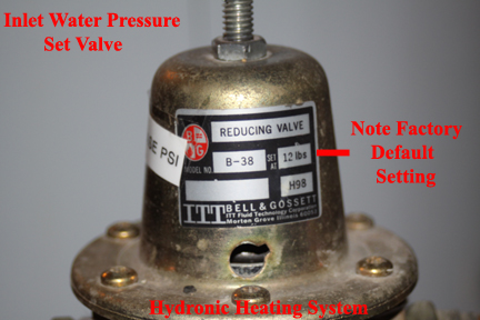
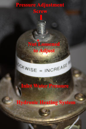
- Pressure Regulator. House water pressure can vary significantly and thus an inlet water pressure regulator is required to define the water pressure in the heating system. I emphasis here that it is this regulator that defines water pressure in your heating system. If your water pressure in your system is too high, you have to manually adjust the pressure regulator for a lower water pressure. If your system has too low a water pressure, you may hear water moving through baseboard radiators and need to adjust the inlet water pressure regulator to allow a high system water pressure.
- Pump. Obviously heating water must be move through the system and a pump or pump(s) are used to do this.
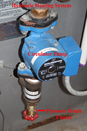
- Drain faucet. Below the circulator pump, should be a drain faucet. The real purpose of this faucet is to allow system water pressure to be reduced. Suppose for example that the inlet water pressure regulator is set too high and the pressure relief valve keeps opening and venting water and thus pressure, you will needed to change the water inlet pressure valve to lower system pressure and then you will need to drain some water out of the system using the drain faucet just below the circulator pump.
- Furnace. Also known as a boiler although boiler is technically incorrect as water is never boiled in a hydronic heating system.
- Pressure Relief Valve. Should something happen where water is being heating and the pressure in the system reaches a dangerous value, this valve opens up, releasing water. How could this happen? In my system, the pressure relief valve is fixed for 35 pounds per square inch (PSI). If I were to change the inlet water pressure regulator, to say have 34 PSI of pressure in my system when the system was cold, when the system heated water, the pressure in the system would build to 35PSI or more and the pressure relief valve would open, releasing water and thus pressure in the system. If you discover a pool of water beside your furnace but can not determine the source, it is possible the pressure relief valve is venting water during the night or during some period and by the time you discover the pool of water, the drip from the relief valve has stopped and there is no clear indication that this valve has opened.


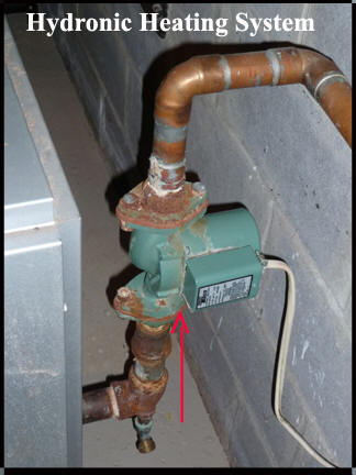
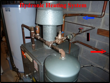
Image above is a different system but you can see the over pressure valve on top of the furnace and how it can drain into a white pan on the left.
- Expansion Tank Shut-off Valve. To allow annual draining of the expansion tank, without negatively impacting system water pressure, the expansion tank has a shut-off valve that shuts down heated water flow from the system.

- Expansion Tank. When confined water, such as in the piping of your hydronic heating system is heated, the water expands. If the expanding water has no place to go, system pressure increases. To smooth out water pressure increases due to water heating, an expansion tank is used. The expansion tank is basically an overflow for system water as water is heated and expanded.
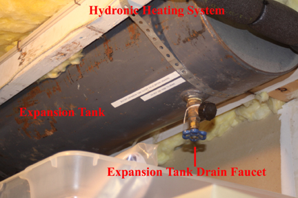
In image above, a different configuration with a different type expansion tank.
- Baseboard Radiators. One would think that a "baseboard radiator" is a "baseboard radiator" but actually, baseboard radiators vary considerable in construction and their heat dissipation rate. If you are updating a hydronic heating system and going to replace baseboard radiators, take some interest and do some research and do not simply leave up the the plumber to make the decision as to the manufacturer of the radiators.

- Zone. In a single floor home, it is normal for one thermostat to control the furnace and thus send heated water to every room of the home. However, in a multi-floor home, it is more common to have a thermostat on each floor, which controls a zone control valve. Thus heated water is only sent to a floor or zone when the thermostat for that floor "calls" for heat. In my home, 3 floors, I have 3 zones.
2. A single zone but 2 loops system. This sort of configuration is normally found in a larger, single story home.

- Loops. Each baseboard radiator drops the temperature of system heated water as water flows through it. In a large home, if all radiators were connected together such that hot water came in one end and exited back to the furnace at the other end, the first radiator would give off a lot of heat while the last radiator would give off very little. Thus in larger homes, radiators are connected to pipe loops. For example, in a 4 room, single floor home, rooms 1 and 2 may be on one pipe loop and rooms 3 and 4 on another pipe loop. A loop is not a zone. A single zone can have multiple loops.
3. A 2 zone system (1 loop per zone). As stated above, to give the homeowner more control as to what part of his home is heated when, zones are used. The best example of this where the house has 2 floors. Each floor has it's own thermostat and furnace piping mounted zone control valve. If a thermostat on one floor calls for heat, the furnace responds but sending heated water only to the floor where heat is wanted.
- Automatic Air Vent. A hydronic heating system may have automatic air bleed vent(s). These vents can be on return lines near the furnace or they be located at one end of a baseboard radiator or a system may not have any automatic air bleed vent(s). There is a screw cap on each automatic air vent. This cap must be unscrewed enough for the holes in the side of it to allow air to be vented. Over time, some automatic air vents begin to leak water and must be replaced. Replacement is not difficult and automatic air vents are readily available.

- Black Flow Restrictor or Valve. A system with zones may have back flow restrictors on the "return" lines going to the furnace. These backflow restrictors only allow water to return to the furnace, meaning that inlet water can not go up the return line into the zone.
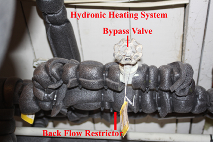
- Bypass Valve. Where there are Zone piping and back flow restrictors, there may also be back flow restrictor bypass valves. These valves are normally closed but can be opened as part of a back flush or system fill operation.
- Zone Control Valve. Homes having more than one floor or very large single floor homes may have 2 or more zones. Typically, there is a zone for each floor. To allow heated water to flow to radiators only on one floor or zone, a zone control valve is used. These electrically operated valves are normally closed but when commanded by the furnace control unit, open, allowing heated water to flow in the defined zone. Every zone control valve I have seen has a lever on top, which allows for manually opening the valve. This lever is not normally used except in a a system air purge operation.
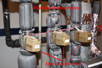
The image above shows another multiple zone configuration. In this case, 5 zones and 5 zone control valves.
- Zone Drain Faucet and Shut-off Valve. Per zone and even per loop per zone, there is a zone or loop shut-off valve as well as a drain faucet. Normally the drain faucet is closed and the zone or loop shut-off valve is open. The zone or loop shut-off valve and zone or loop drain faucet is only used in a system water drain, back flush or system air bleed operation.
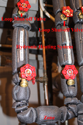
Note that although I have not tried it yet, it should be possible to close off one loop if heat is never needed in that portion of the house. For example, my bedrooms top floor has 2 loops. By closing the loop valve for the loop that services unused bedrooms, I should be able to save energy. This of course, depends on how well the loop with heat works in making air temperature rise enough for the thermostat to stop demanding heat in the portion of the floor I am heating.
- Whole House Air Scoop. Most hydronic heating systems do not have a whole house air scoop. Setting on the output pipe of the furnace, before the zone control valves the whole house air scoop captures air trapped in system water and vents it out of the system. After trying many different approaches to getting air out of my 3 zone system, I installed the whole house air scoop and then performed an air bleed operation. I am very happy with the whole house air scoop.
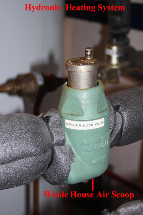
In image above, a different system, there is no whole house air scope. Note the automatic air bleed valve on the water inlet line. This might serve as a whole house air bleed valve but no where as good as a "scoop".
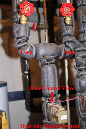
4. A 2 Zone, with loops.
The image above shows a zone control valve before 2 loops.
5. A 2 Zone, with loops and multiple pumps.
I have seen older hydronic systems that have one circulator pump per zone.
6. A 3 Zones System.
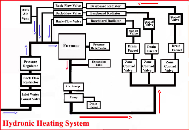
There is nothing unique about a 3 or more zone hydronic system. Just more pipes and valves and operations like back flush and air bleed become a little more complicated.
7. A 3 Zones with Loops System.

Once again, there is nothing unique about a multiple zone, multiple loops hydronic heating system.
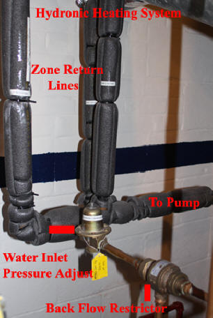
The image abovc shows the 3 zone lines of my 3 zone system returning to the furnace. Not that inlet water also joins the single pipe here leading to the pump and eventually the furnace.
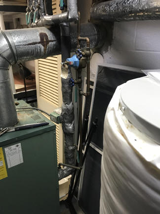
Below are 2 images of my 3 zone, multiple loops, single circulator pump, system.
.jpg)
.jpg)
Different Configurtations:
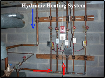
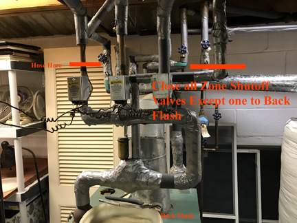
As mentioned throughout, almost every installation is different in some way. Below are images of another system.
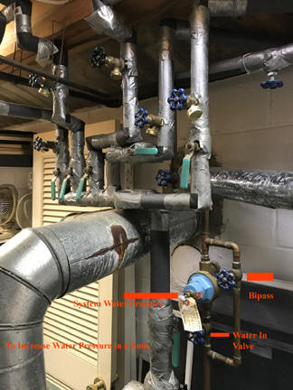
Image above shows zone shutoff valves and spigots for back flush installed on return lines.
Also shows bypass installed around system inlet water pressure regulator which is a great idea when one zone or loop has an air block.
Summary.
As explained when I started this, there are many possible hydronic heating system piping, valve, pump, etc combinations or configurations. Certainly, at first sight, a hydronic heating system can appear to be a nightmare of pipes and valves but if you take the time to sort it all out, hydronic heating is not that complicated. In other documents I describe other aspects of hydronic heating.
Finally, pipes. The pipe used in a home hydronic system can be cast iron or copper or a combination of both. I have heard of leaks developing in a hydronic heating system but have not experienced such a leak in my own system.