Shared Knowledge
"HVAC - Forced Hot Air - Do-it-Yourself (DIY) Replace Lennox Harmony II with Harmony III Control Board"
13 January 2019
Summary: can be done DIY but might require HVAC tech to come in after install to get it 100% so plan on 2 days of no heat or AC.
Background:
Moved in 2018 into a house with Lennox signature 2-stage natural gas fired furnace with variable speed blower, 3 ton, 2-stage, AC compressor, 3 zone air duct system and Lennox Harmony II control board.
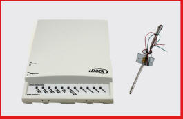
Harmony II throwing discharge air sensor (DAS) bad error message.
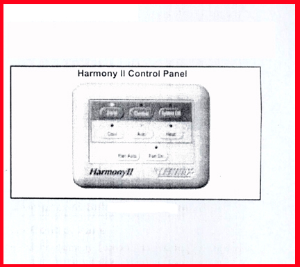
When DAS bad, Harmony II goes into "centralized" mode or thermostat 1 controls temperature of all zones.
Searched for Harmony II DAS replacement but could not find anywhere.
Searched for specifications on DAS to buy an equivalent (temperature verses resistance) but could not find.
Contacted Lennox dealer to replace Harmony II with Harmony III but tech who visited said they would use Honeywell zone control board and wanted to replace 3 existing dampers with new Honeywell for $2500!
After learning more about Lennox, forced air zone systems and Harmony II, decided to replace Harmony II with Harmony III myself.
Do It Yourself?:
Can you do it yourself? This is not an easy job. Requires removing and reattaching a lot of wires and potentially adding a transformer to your indoor blower unit. None of the wires that have to be moved carry high voltage but many to deal with so bottom line, have to be organized, take your time and count on..... when you all done, system will not work as desired and still going to need HVAC tech to make it right.
If you handy and have done electrical wiring before and not afraid to cut some drywall and have a cable labeling system, at least consider it.
If you have not worked with wiring, don't have a voltmeter and know nothing about circuits and your current system, pay a HVAC tech to replace for you. Expect to pay $1400-$2000 which includes Harmony III board cost.
How to do it yourself:
Can not detail every step I used to replace Harmony II with Harmony III but am going to try to provide the "harder to gleam or understand" aspects of the job. Of course your configuration could and probably is different.....
Harmony III control board can be had from multiple sources on the Internet. Harmony III comes with new DAS. Prices range for new, $200 off eBay to $600. Do not buy a used Harmony III.
What you might or are going to need:
Time. Do not shoehorn yourself into a tight time schedule. Do some, back off, break, go away and then come back and double check your work before beginning a new task.
Phillips screwdriver (maybe several of different sizes).
Wire cutters.
Sharp knife or box cutter to strip insulation.
Very small flat blade screw driver to hook, unhook, wires from control board connectors.
Several feet of 3 conductor thermostat wire (may have to lengthen some existing wires).
Perhaps a shrink wrap tubing kit. If you have to lengthen some wires, going to want to properly insulate junction with shrink wrap tubing (could use small wire caps or even electrical tape but think long term and use shrink wrap tubing).
Label maker or someway to label wires.
Perhaps some very small wire caps.
Voltmeter (must have).
Considerations:
Thermostats. My system is a 2 stage AC and 2 stage heat system. I use (3) T2 thermostats to control 3 zones. The Harmony III gets signals from thermostats and if setup for 2 stages, tells AC or heat to go to second stage after a time delay. I.E. no second stage wire is required from any thermostat although thermostats must be setup to work with 2 stage system. Point being, you need to check your thermostat and see if all wires on the Harmony II for thermostats are actually in place. If there are open connections on the Harmony II for a thermostat wire, you need to check your thermostat to ensure it will work with a Harmony III.
Dampers, Harmony III 24VAC transformer. There is a separate 24VAC transformer in the blower unit that supplies power to the Harmony III. The Harmony III provides power to all dampers. In my case, I had 3 dampers in my 3 zone system (all on output side of blower) but no dampers on the return lines and wanted to add dampers on returns. Very clear that the stock, off the shelf, transformer normally installed with a Harmony II would not power 5 dampers (no damper on main zone return line). Thus, I had to buy and install a "larger" 24VAC Harmony III control board transformer. This is relatively easy but must be careful and check that Harmony III transformer is in phase with indoor and outdoor equipment transformer installed on furnace control board.
Physically Mount Harmony III:
Before doing anything else, remove cover from Harmony II and using a label maker or what ever method you choose to label each and every wire. Also using a diagram of Harmony II, define which color cable wire goes to which labeled terminal on board.
Turn off power to Harmony II. How might not be obvious. In my case, power is supplied to Harmony II via cables (2) from blower unit in attic. By using emergency shut-off switch located near blower, this killed both lines of 24volts alternating current (VAC) to the Harmony II. With a voltmeter check that both 24VAC lines are dead at Harmony II before proceeding.
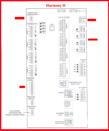
IMPORTANT: THERE ARE TWO (2) 24VAC POWER LINES GOING TO THE HARMONY II CONTROL BOARD. ONE IS "DAMPER POWER" IN UPPER RIGHT HAND CORNER AND THE OTHER IS ON UPPER LEFT SIDE OF BOARD, "INDOOR UNIT TRANSFORMER". WHILE THERE IS NO POLARITY TO AC, THERE IS PHASING AND YOU MUST FIND THE 24VAC LINES AND LABEL EACH LINE'S WIRES (+) AND (-) AS THEY ARE CONNECTED TO (+) AND (-) CONNECTIONS ON HARMONY II.
As Harmony II control panel is not used by Harmony III, remove it. Top cover just pops off and then remove wires from base and remove base.
With all wires labeled and color of wires marked on old Harmony II wiring diagram, use small flat blade to loosen all wires from Harmony II connectors and pull cable or wire out enough so wires will not interfere with board removal.
With wires disconnected from Harmony II, remove all mounting screws that go through board into drywall except for one at the top.
Now, holding board at bottom, remove one remaining screw and pull Harmony II board out, away, from wall.
The Harmony III board is physically smaller than the old Harmony II. You can use one of the existing Harmony II mounting holes or simply position the Harmony III over the area that held the Harmony II and then mount the Harmony III. This is what I did to ensure I had enough room at the bottom to properly drywall patch the holes no longer needed there. As the Harmony III weighs next to nothing, do not need hallow wall anchors to hold mounting screws. At this time, I also marked the 4 holes in the Harmony III where cables and wires are supposed to come through the board and used a drill to make holes in the drywall. Do not mount Harmony III as this time.
Once Harmony III mounting and cable access holes are in place, define with a pencil, a rectangular box behind the board and cut it out with a box cutter or other. This hole will give you access to all cables that go to the Harmony III. You want a hole large enough to reach into but no so large as to be visible from the edge of the mounted Harmony III.
With large hole in drywall, I found all wires (thermostats, discharge air sensor, 24volts alternating current (VAC), damper control lines, "inside" and "outside" equipment and control cable from Harmony to furnace control board) inside hole and slowly pulled each out of its current drywall hole, being careful to not nick the insulation of any cable.
With hole cut, find each cable and insert it through the board access hole. Of course idea here is to route all damper cables near Harmony III damper connections, equipment cables near board equipment terminals, etc. Damper power cable should be in upper right corner and "indoor transformer" power cable should come through lower right hand corner board hole.
Now examine wires of each cable. In some cases, wires might be too short after moving or too long. Here, you might have to add length to one or more wires by using some thermostat wire. Just be sure to cover any and all wire junction well. I prefer shrink wrap tubing for this. Make sure junction is mechanically strong before insulating.
If a cable is too long, peel back some cable sheath and make wires correct length.
Be careful to not nick the sheath of any cable or insulation on a wire.
With cables and wires correct length, take Harmony III board to wall and route all wires and cable through wire access holes in board and then mount Harmony III to wall.
Image below shows Harmony III mounted with various cables coming though correct holes in drywall and holes in Harmony III board.
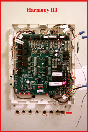
Note: by looking at image above of new Harmony III in place, how most wires came through drywall at bottom of old Harmony II board. Actually came through 2X4 at this location. Eventually will cut out section of drywall here and drywall mud shut, sand and paint.
Note: labels on wires.
DAS:
The Harmony III comes with a new discharge air sensor (DAS) that you must use. Depending on what DAS you currently have, the new DAS might mount right up to the blower or it may not. In my case, I had to remove old DAS completely, remove actual sensor and then insert new sensor into old mounting plate.
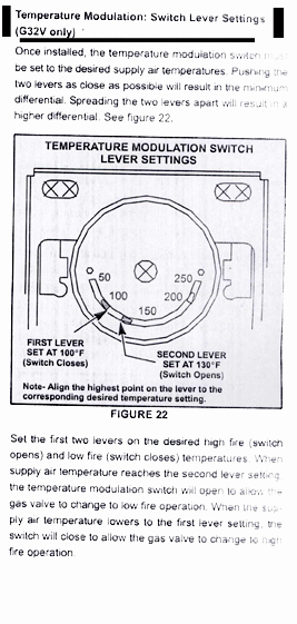
Temperature Modulation Switch:
I did not know until after Harmony III was installed and service tech got system going that there was a Lennox temperature modulation switch installed in the blower (service tech did not know what it was or did). As there is no mention of it in Harmony III documentation, I removed switch and discarded.
This switch was installed in blower above coiling coils and had a large probe or sensor sticking into air stream. I assume if you have one, you can leave it in place if you wish. Unclear how to wire to Harmony III. Does not appear to be needed. I do not have a picture of actual switch.
Harmony III Electrical Connections:
With cables, wires, labeled, you should be able to attach various to the Harmony III easily (other than perhaps having to strip some insulation, shorten or lengthen wires, etc) but there are 2 main electrical connection differences between Harmony II and Harmony III:
(1) Damper connections. The older Harmony II has only 2 connections per damper. In most cases, installed dampers are of the normally open, powered close (NO) type, and the Harmony II was setup to handle this type of damper, ie. only 2 terminals per damper. However, the Harmony III can handle both (NO) as well as the normally closed, powered open types (NC) of dampers. Again, wires that connect dampers on the old Harmony II were by default for the NO type. So when you connect the damper wires to the Harmony III, must use the common terminal and the "NO" terminal.
The image below shows damper connections and "Common", NO (normally open, powered close) and NC (normally closed, powered open).
Note: On Damper 1, I have both a NO and a NC damper connections. As 3 wire damper cable is used, one cable can control both a NO and NC damper installed in the same zone.
Also note that instead of labeling zone 1, 2 or 3, I actually labeled dampers according to what rooms or areas for easier understanding by anyone not familiar with my system.
.jpg)
(2) Equipment power. The old Harmony II had connections for both "damper power" as well as "indoor power transformer", whereas the Harmony III only has a connector marked "damper power" in upper right hand corner of board. When I installed the Harmony III. I overlooked this aspect and when I powered up the board for the first time, although the board appeared to operate correctly, the AC compressor did not run. At this point, not knowing enough, I had to call in a service technician who finally sorted out that "equipment" was not getting 24VAC control signal from Harmony III and attached "indoor power transformer" to terminals label equipment
.jpg)
Below shows that 24VAC from "indoor power transformer" (+) wire connected to both "indoor" and "outdoor" equipment terminals.
The (-) line from 24VAC from "indoor power transfomer" must be connected to the black or "common" wire of the outdoor unit.

Note: I do not show how existing wiring going to "indoor" and "outdoor" equipment terminals as you must connect as you found off old Harmony II board. Color of wires could be different from my system.
Note: "Y1" is first stage AC, while "Y2" is second stage AC. You may only have a "Y1" wire if your compressor is only a single stage.
Note: "W1" is first stage heat while "W2" is second stage heat. You may only have a "W1" wire if your burner unit has only 1 speed.
Normal operation:
Can not define every aspect of normal Harmony III control board operation but need to make these points:
When a thermostat calls for heat:
- Harmony III closes dampers on zones not calling.
- After a time delay, Harmony III connects "indoor power transformer" to "W1" which commands the the furnace control board to fire up the burners.
- Harmony III then monitors the DAS and when it has reaches (160F) (can change via board settings), the Harmony III commands the indoor blower unit via the "G" terminal to begin blowing air. If after a period of time, demand is not met, Harmony III connects "indoor power transformer" power to the "W2" terminal and commands the blower to ramp up speed. (Speed is function of board settings for each zone).
- Once demand is met, power is removed from W1 and W2 but the blower continues to run for a furnace control board, defined time.
- Finally, the Harmony III removes all power from damper control terminals allowing dampers to return to their "normal", non-powered states.
When a thermostat calls for AC:
- Harmony III closes dampers on zones not calling.
- After a time delay, Harmony III connects "indoor power transformer" to "Y1" which commands the AC compressor to begin to run.
- Harmony III then monitors the DAS and when the DAS reaches 55F (adjustable via jumpers on board), via the blower terminal "G" connection, commands the blower unit be begin to blow air.
- After a defined period of time, if demand has not been met, the Harmony III commands the blower to ramp up speed (amount adjustable per zone on Harmony III).
- In 2-stage system, if "demand" is not met (thermostat still demanding) within a time delay, non-adjustable, period, the Harmony III connects "indoor power transformer" power to "Y2" kicking in the second stage of the compressor.
- Once demand has been met, according to demanding thermostat, the Harmony III disconnects "Y1" and "Y2" from "indoor power transformer" shutting compressor down.
- The blower continues to run for an indoor blower control board setting and then turns off the fan or blower.
- Finally, the Harmony III disconnects all damper power allowing all dampers to return to their normal, non-powered states.