Shared Knowledge
" HVAC Zoned Forced Air System - Overview"
Summary: Although home forced air heating and cooling (HVAC) at first glance can appear a mystery, really there only so many components and many are easy do-it-yourself (DIY) repair or replace.
Background:
Moved into a house with Lennox, 3 zones, forced air, both air conditioning (AC) and natural gas heating. Previous house had zoned hydronic heating and 2 AC units and one heat pump, so unfamiliar with a zoned forced air system. Did not want to learn about system but after repeated hiring of local "Lennox experts" with mixed results, had to learn system myself.
HVAC Forced Air System Components:
Now matter the brand, the major components of a zoned forced air system include: an outside compressor or heat pump unit; an indoor air handler or blower which may or may not also include a furnace of some type (natural gas); a furnace\blower control board; one or more 24 volts alternating current (VAC) transformers, a zone control board; discharge air sensor; thermostats; piping or ducts to and from blower unit; return grills; output vents and dampers or air control valves in pipes or ducts to outlet vents.
Zoned System:
In a small house, a single AC unit and single heating unit and one thermostat is usually all that is required.
In a larger house, such as in the case of a 3 story with each floor needing both heat and AC but perhaps not all at the same time or same temperature, one approach is to install a thermostat on each floor and then one AC unit and one heat unit per floor. Although some houses are built this way, 3 AC and heating units are expensive to buy and install so this is where a zoned system comes in.
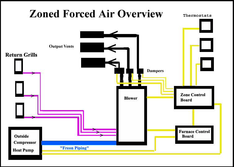
In a zoned system, a single AC unit and heating unit is controlled by multiple thermostats and duct work with zone control valves or dampers in them to restrict or allow air flow in each zone As one can not simply connect 3 thermostats directly to a furnace control board, a zone control board is required. With a zone control board, the board responds to thermostat demands for heating or cooling and commands the furnace control board and outside AC as needed.
The diagram blow shows a typical zoned forced air system.
24 VAC Transformers: All equipment to heat or cool you home is controlled by 24VAC which comes from one or more 24VAC transformers. 24VAC is industry standard for control systems. For example, 24VAC is supplied to your thermostat and when the thermostat demands cooling, it closes a relay that supplies 24VAC to the outside AC compressor unit as well as the blower unit. In some systems, two (2) 24VAC transformers are required. The location of transformers are usually in the inside blower unit, perhaps behind a sheet metal panel. If you system is completely dead, check the circuit breakers for both the outside compressor unit as well as the blower unit and then if still nothing, find the 24VAC transformer and check that it is supplying the required 24VAC to all control circuits. Transformers do fail, especially when they are not rated to supply all the current your system is requiring.
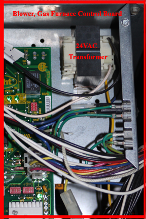
Below shows the 24VAC transformer mounted on the furnace control board. It supplies 24VAC to control lines to the compressor unit, the blower unit and all thermostats. In general, 24VAC transformers are found in the blower unit or stack.
Because the any zone control board installed supplies 24VAC to motorized dampers, an additional 24VAC transformer is required. This transformer must be able to supply enough current to power as many motorized dampers as you have in a system. 5 motorized dampers can be handled by a high current, 75 volt amp (VA) transformer. More than 5 motorized dampers and special transformers or wiring is required.
Below shows the Harmony III zone control board dedicated 24VAC transformer installed in the blower unit.
![]()
Although there is no polarity with AC like found in direct current (DC), depending on how the zone control board connects to the furnace control board, the phasing of the 2 transformers must be considered. 2 transformers must be in phase with eachother.
AC or Heatpump outside compressor: Outside of your home is a large rectangular or square unit. This unit can be simply for air conditioning and work to supply cool air to the inside of your home or it can be a heat pump that can supply both cool and heat to the inside of your home. This unit is controlled by 24VAC control wires but uses 240VAC to actually run the compressor motor. 240VAC can easily kill you so if you have no experience working around very high voltage, do not open your compressor unit. If the unit outside is a heat pump, a control board is inside that responds to thermostat or control board settings for heat or cool.
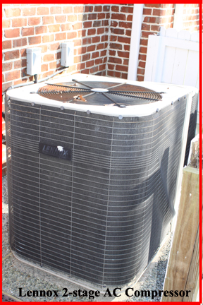
Below is an image of a 2 stage Lennox AC
compressor. Stages: most AC compressors have only one compressor and thus have
only 1 "ton of cooling" rating. In some larger houses, if a unit was ton-sized
to handle the worst case outside air temperature, it would potentially draw a
lot of electricity even on cooler days and thus not be efficient. With a 2 stage
compressor, the first stage runs most of the time but when outside air
temperature becomes extreme and the first stage compressor can not keep the
temperature inside at a thermostat set point, a second stage compressor is
energized. In my case, the first stage compressor is rated at 3 tons but when
the second stage compressor is engaged, the entire unit is rated at 5 tons of
cooling. Whether or not you have a single, 2 or even 3 stage compressor can be
found by taking the model number off the unit and doing an Internet search on
specifications.
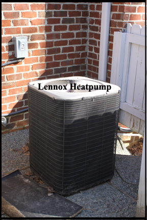
Below is an image of a Lennox heatpump.
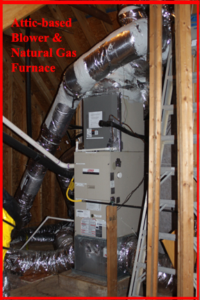
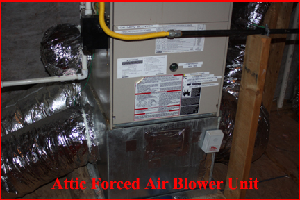
Blower unit: This unit is usually located in an attic and is a tall or long rectangular box with hoses or metal duct work attached to the bottom or one end of it and additional hoses or duct work attached at the top or other end of the box. Invisible to you, behind a sheet metal panel is a "coil set" that either gets cold when the AC is running or hot if you have a hear pump. If you have a heat pump, the blower unit simply has a small control board that turns the blower motor on and off. In my case, I have a natural gas furnace built into blower unit and with it a gas furnace control board. When a thermostat demands heat, the blower unit control boards opens a natural gas valve, sparks an gas igniter and waits for some time to ensure natural gas is actually burning before opening the gas valve to the other burners in the unit. This control board has some blower speed control functions.
Below is an image of my attic-based blower unit. In my case, it includes a natural gas furnace. In my case the blower unit is upright but you might find your blower unit in a closet, in a basement or perhaps horizontally mounted. All air ducts originate from or terminate to the blower unit.
Blower: The actual blower motor inside a blower unit can be of several varieties to include: single speed, variable speed and variable speed with pressure sensor control. A single speed is as implied, the blower turns on, rev's up to its defined speed and stays there. A variable speed blower allows for various zones to have less blower volume output. Finally, a variable speed blower with pressure sensors, rev's up to a defined speed and then responds to changes in system air pressure, such the opening or closing of duct vents, all with the idea of keeping the same defined blower speed, no matter the air duct scenario.
Below is an image showing the blower control board and the gray sheet metal housing of the blower unit. On the left side of the gray sheet metal is an opening and on the right side the actual motor is mounted to a squirrel cage fan that sucks air in from the left side and exhausts it up through any gas furnace or AC coil set into zone ducts. Also note the black, interlock switch mounted on the upper left hand corner of the furnace control board. If you need to work on the furnace control board or gas furnace above it, you will have to tape shut or otherwise ensure this switch is pushed in or the blower unit will not work.
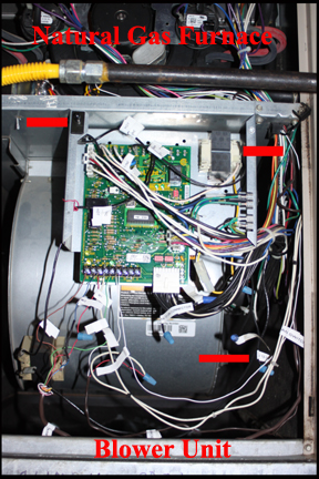
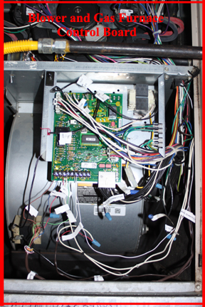
Blower/furnace Control Board: In my case, I have a gas furnace in my blower "stack" and thus a control board that controls the natural gas furnace and the actual air blower. If you have a heat pump, there is a control board in the outside heat pump unit and also some sort of blower control installed in the blower "Stack". Below shows several images of my blower unit natural gas and blower motor control board.
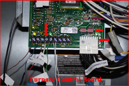
In this image, dipswitches (red block with white up or down switches) on the control board are shows that allow for various modifications of furnace and blower operation depending characteristics of home installed in. Also show is the large white connector that connects the control board to the actual blower unit directly behind it. Finally, this image shows a screw terminal strip at the bottom where connections from the zone control board are made. Dipswitch settings will be unique for your system as well as wiring on the terminal strip. If you have the manual for the blower unit, you can find information in it about various settings and connections. Just make sure you have the manual for the blower unit actually installed in your home.
Zone Control Board: Again, in a zoned system, there is only one AC compressor. one heating unit and one blower unit but multiple thermostats, thus there must be something between the furnace and AC unit that allows each thermostat to demand cool or heat as needed for a specific zone. Thus the zone control board.
In general, all thermostats connect directly to the zone control board and circuits on the board respond to thermostats to control the furnace heating unit or the outside AC compressor as well as the blower unit and all installed motorized dampers. Although there are probably as many zone control boards as there are manufacturers of home HVAC systems that can be zoned, I am familiar with the Lennox and Honeywell.
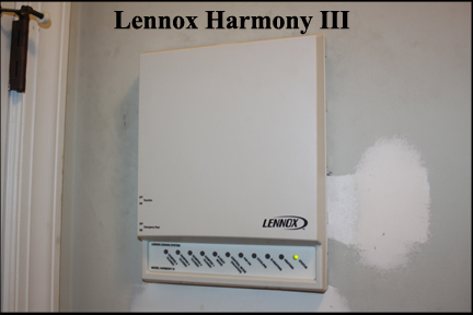
Below is an image of the Lennox Harmony III control board I have installed in a closet on the 3rd floor. Zone control boards can be installed anywhere to include right beside the attic-based blower unit.
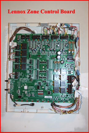
Below is an image of my Lennox Harmony III zone control board with the cosmetic cover removed.
Again, no matter your zoned forced air system, you will have a zone control board that accepts thermostat inputs and control wires to both the outside compressor unit, the blower and perhaps a furnace of some type. The zone control board will also command all installed motorized dampers.
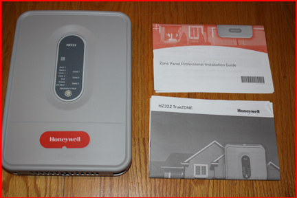
Below is an image of a Honeywell zone control board.
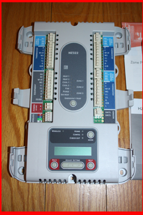
Below is an image of a Honeywell zone control board with cosmetic cover removed.
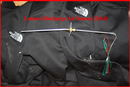
Discharge Air Sensor: No matter the manufacturer, all zone control systems have a discharge air sensor (DAS). The DAS is a probe that extends into the blower output stream before any zone dampers and reports air temperature to the zone control board. In some cases, the DAS is used only to detect extreme cold air approaching the temperature where the AC coils might begin to freeze over. In this case, the zone control board shuts down the AC compressor until the DAS is not reporting extreme cold air. In other systems, such as my Lennox, the DAS monitors for extreme cold but also uses DAS reporting to turn on and off the second stage of cooling or the second stage of heating.
Below is an image of a DAS, not installed.
Below is a picture of a DAS installed in duct work right off the top of the blower unit.
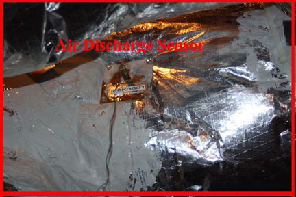
Note here, that I have found most HVAC technicians think that a DAS only monitors for a AC frozen coil. Depending on your zone control board and its operation, this may or may not be true.
Thermostats: Thermostats are made by many different manufacturers and come in many different varies from the very simply to WiFi controlled but all do the same function: command the AC or furnace and perhaps independently provide some continuous blower control. Although thermostat wiring might appear complex, it is not. Wires W1 and W2 command heat with W1 basic heat and W2 additional heat. Y1 and Y2 command AC with Y1 basic AC and Y2 secondary AC. In addition there is a ground wire and a 24VAC wire and that is it. Replacement of a thermostat is certainly a do-it-yourself (DIY) job.
Note here that before you buy a replacement thermostat, make sure it can control what your system needs in the way of control functions. For example, some thermostats can only control 1 stage cooling or heat.
Duct Work: Pretty obvious but into and out of the blower unit must be duct work for forced air flow. Duct work to include sizing of ducts, locations of return vents, location of output vents and location of dampers or air flow control devices is dictated by the architecture of a structure. In most home installations, the major duct work is in the attic with flexible ducts used to connect return ducts and output vent ducts.
Forced air is a closed system. This means air is sucked out of a space by a return vent and heated or cooled air is then sent to output vents in the space or zone demanding heat or cool.
Below shows return or suction duct work going into the bottom of the attic-based blower unit. The major return duct for the largest zone is shown on the right side of the blower unit while a smaller 12inch return for a smaller zone is shown on the left side as will as an even smaller 10 inch return from the smallest zone in my home.
Below shows return ducts bringing air from 3 zones back to the blower unit
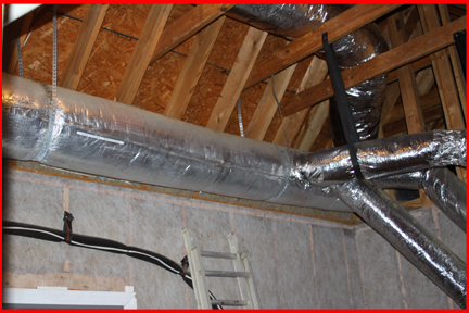
Below shows the duct work associated with the largest zone in my home. As can be seen off the main, metal, round, insulated, duct, smaller ducts come off to supply heated or cooled air to varies rooms of a large zone. Although in my case duct work is round, it can also be rectangular.
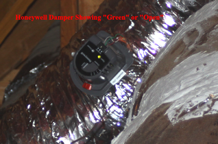
Zone Control Valves or Dampers: So each zone in a forced air zone system has its own return duct work and its own output duct work off a single blower. With only one blower but multiple thermostats, zone control valves or dampers are used in duct work to allow or restrict output air flow. These valves are usually normally open, powered close and use 24VAC from the zone control board. When only one zone calls for heat or cool, the zone control board closes all dampers in duct work going to zones not requiring heat or cool and leaves the damper in the zone calling for heat or cool open. There are various manufacturers of dampers but Honeywell is one of the more common.
The image below shows a Honeywell damper of the normally open, powered close type.
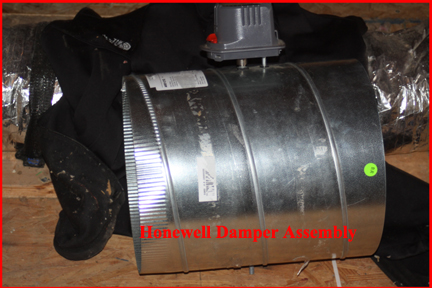
Below is an image of a complete zone damper assembly.
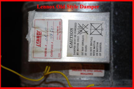
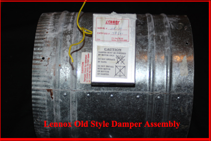
Below is an image of an old style damper.
This has been intended as only an introduction to a zoned forced air home hearing and cooling system. Additional details about specific components can be found in other articles in this section.