Shared Knowledge
"HVAC Zoned Forced Air System - Dampers Overview"
19 January 2020
Summary: The purpose of a zoned forced air damper is to allow or restrict air flow through it. There are 3 types of dampers used in zoned forced air systems: (1) A manual, variable position but fixed position damper; (2) a motorized damper and (3) a bypass damper. A damper is actually an assembly to include a sheet metal section, a plate on a shaft inside the sheet metal assembly and then some sort of plate movement device be it a fixed arm, motor or air pressure. As duct sizes vary depending on zone sizes, damper assemblies must be the same size as the duct work they are installed in.
Background: In a zoned forced air heating and cooling system, one air conditioning unit (AC), one heating unit and one blower unit supplies heated or cooled air to an entire house via ductwork. As typically, the heating and cooling requirements of a larger house are not the same everywhere, separate duct work is run from the top of blower unit into separate areas or zones. By adding a thermostat in each separately ducted zone and via a zone control board that "sits" between all thermostats and the AC, heating and blower unit, the zone control board can allow or restrict blower air via a motorized damper.
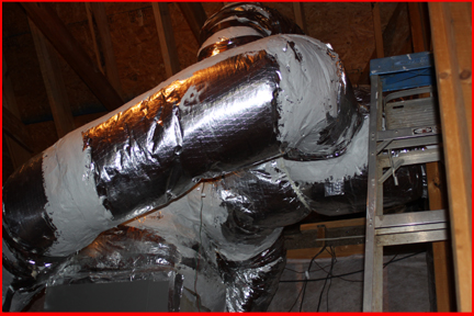
Below shows 3 separate ducts coming off the attic-based blower unit. Again, in each of the 3, there is a motorized damper than either allows or restricts air flow.
Dampers: There are potentially 3 types of dampers found in forced air zoned system: manual, with adjusted but fixed position, motor controlled dampers and bypass dampers. A manual, adjustable but fixed position damper can be found in areas where it is easy to open or close the damper by hand, such as in a rarely used unfinished basement. Another use for a manual, adjustable but fixed damper is in an air return duct. In this case, return air can be limited from one zone such that the blower sucks more air from other zone returns vents. In either case, manual or motor controlled, inside the duct work is a plate that moves from open to closed or closed to open.
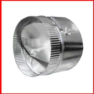
Below is an example of a manual damper. To adjust air flow through this damper, the wing-nut is loosened, the lever moved to adjust plate inside and then wing-nut is tightened.
In the case of a motorized damper, the plate inside the damper assembly can be either normally open, power closed or the opposite. Most installations use the normally open (NO) type damper. When a single thermostat in a multi-zone system calls for heat or cool, the zone control board applies 24 volts alternating current (VAC) to the terminals of all dampers in zones not requiring heat or cool, thus closing off air flow. Although it would be extremely rare to find a motorized damper using 110 VAC, before doing anything on a damper, check damper closed voltage at the damper.
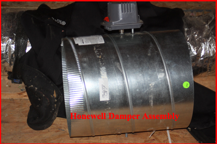
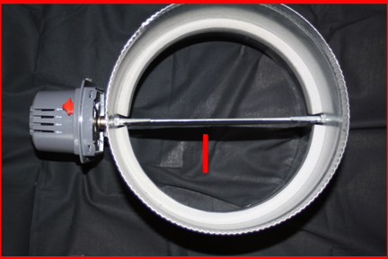
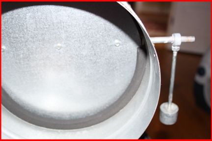
Below is a Honeywell motorized damper assembly in the open, or free air flow position.
Looking down into a complete assembly. Note that there is no spring inside the damper assembly. The spring in the newer Honeywell motorized dampers are in the motor "head"
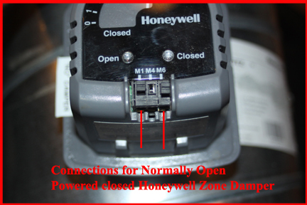
Once again, dampers in a multiple zone forced air system are controlled by a zone control board that applies 24VAC to the terminals of all dampers that need to be closed during a heating or cooling operation. Blow shows the damper control terminals on the newer-type NO damper. In this case, M1 is the common from the zone control board and M6 is 24VAC. The M4 terminal can be energized if you want the "open" and "closed" LED's to function
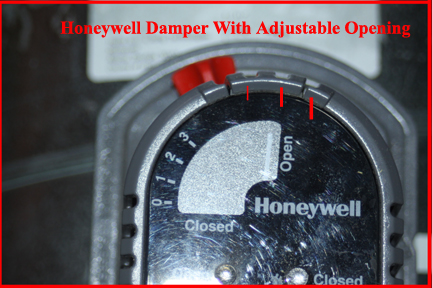
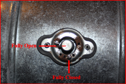
Powered dampers allow for some adjustment between fully open and fully closed. There are times, when a small zone calls for air, a damper in a larger duct may be adjusted to mostly close but not all the way. Below shows how the large red thumb-set can be moved from the left to right by pushing down and turning, allowing the plate inside the damper to be closed to the positions defined on the face plate of 0, 1,2 or 3.
Below is an image of an older Honeywell damper assembly in the open position. Again, nothing but a movable plate. In this case, note the spring inside the assembly. If this spring breaks, the complete assembly must be replaced. If the motor for this older type goes bad, motors are still available and an easy DIY but probably up a ladder.
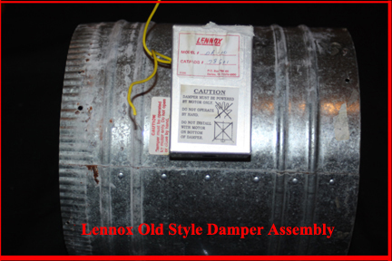
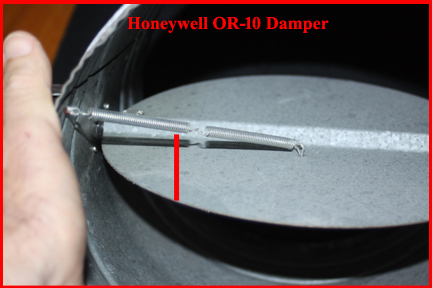
Although not as convenient to use, the older style damper does allow for various partially closed settings. On the assembly side opposite the damper motor, you will find the end of the internal plate shaft and by moving a set screw, adjust how closed you want the damper to be. Again, this adjustment allows some air to pass into other zones when a specific situation demands it.
Finally, a bypass damper. The need for or use of a bypass damper seems to vary from system manufacturer to manufacturer and installer to installer. Some say it is absolutely necessary, others not. The idea is when only one zone is demanding heat or cool, if the blower speed is not adjustable or is set too high, pressure on the blower motor can build up because it is trying to shove too much air down a duct, perhaps with many closed outlet vents and cause the motor to heat up and perhaps die long before it should. Additionally, with a fixed blower speed, the amount of air coming out of a small zone's vents might be too strong or even noisy.
So one solution to control air pressure in a forced air system is to include at the top of the blower stack, another take-off duct that is routed to a by-pass damper that, when needed, shuttles some of the blower air into a return duct. Seems kind'a silly and wasteful recalculating heated or cooled air but this is better than stressing the blower motor. Again, you may have a bypass damper or you may not. If you having a problem with your system for the very first time, a technician may suggest a bypass damper and if so, I suggest you get a second opinion...
Depending on the age of our forced air system, you might have one of the older style bypass dampers installed anywhere in your system. Instead of having a separate duct coming off the top of the blower unit, a bypass damper may be install in the duct work of a small zone that then allows some zone air to return directly to the bottom of the blower assembly.
Below is an old style bypass damper. In this case, a weighted arm is adjusted such that when forced air from the blower overcomes the torque of the weight on the internal damper plate, air is allowed to return to the bottom of the blower unit. These were used for a long time but requires a lot of tinkering to get the weight on the end of the damper plate just the right height on the weight arm for correct damper opening.
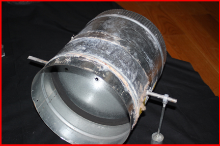
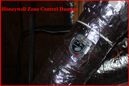
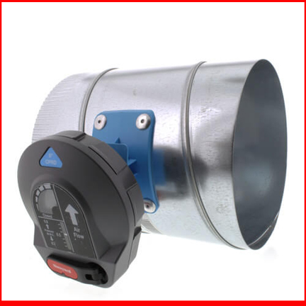
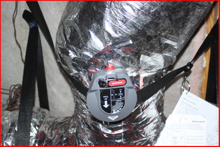
Below is an image of a new type of Honeywell bypass damper. Although difficult to see, the bypass damper's input is coming from a duct off the top of the blower unit and the bypass damper, when open, allows some blower air to return through the lower or return duct to the blower. In this case, the return duct used is the middle size of my 3 zone forced air system.
In the image blow, the bypass damper has opened a little bit due to the blower speed and what zone ducts are open, etc.
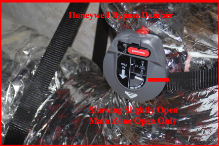
The advantage of the newer type of bypass damper is that it can be easily set when all zones are fully open and that then sets a benchmark on how to respond, or bypass some air depending zone conditions, vents open, etc. No more tinkering with a weighted arm-style bypass damper.
In summary: Zoned forced air systems have multiple output ducts and multiple return ducts. In output ducts, dampers are installed to allow or restrict air flow. Control of dampers in a multiple zone system is accomplished by multiple thermostats and a zone control board.
More Topics on Zone Forced Air HVAC