Shared Knowledge
"Zone Forced Air - Blower"
Summary: In a zoned forced air heating and cooling system, having to have a air blower unit is obvious. But, components of blower unit can vary significantly and include or many include: actual blower motor; gas furnace; air conditioning coils set, a humidifier or dehumidifer, electronic air cleaner and a furnace control board.
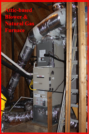
Background: In a zoned forced air system, one blower or fan is used to suck air out of home internal space via return ducts and then cool or heat it and send it out duct work to output vents. A blower unit can be anywhere in a home from the basement, in a closet or in an attic. A blower unit can be mounted vertically or horizontally. But no matter the location or orientation, return ducts enter below the internal fan and output duct work is above the fan.
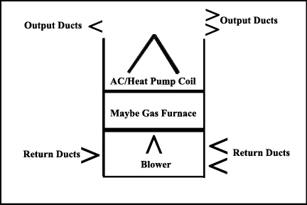
In the image below, the return ducts are show entering the blower unit below the actually blower motor and its housing. In my case, I have 3 zones with one large one, one medium size and finally one small zone. As reflected, somewhat, in the image below, the size of the return flex duct depends on size of zone. But it is important here to understand that in a normal zoned forced air system, there are no dampers or restrictions in return ducts. This means when the blower motor is running, it is sucking air from all zones, not just the one demanding service.
Exception to the rule: in my case, the return on my smallest zone is only about 5 feet from bottom of blower and thus, if left unrestricted, the blower unit sucks more air out of the smallest zone than any other zone. To enhance the suction on the largest and most commonly heated and cooled zone, I have inserted an adjusted plate, manually set, damper in the small zone return line.
Out the top or output end of the blower unit, zone duct work is attached. Each zone gets its own duct work. Whether or not the duct work of a zone actually received heated or cooled air is a function one or more dampers inserted in the duct work of a zone.
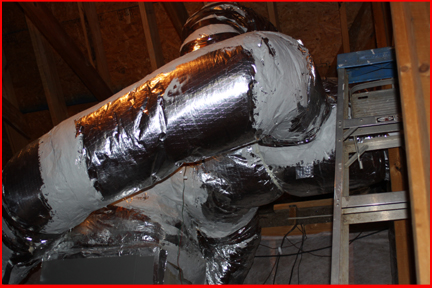
The image below shows 3 different ducts coming off the top of my attic-based, vertically mounted, blower unit. Again, whether or not actual blower air gets out of vents in each duct depends on 1 or more dampers in the duct.
The Blower: The actual blower consists of a sheet metal housing, a squirrel cage fan inside the sheet metal housing and a motor attached to the shaft of the squirrel cage fan. There are many different types of motors to include: a single speed; variable speed and variable speed with constant torque.
A single speed fan motor is just that, a single speed. When the motor is energized, it spins up to a defined revolutions per minute (RPM) and stays there.
A variable speed fan allows for better control of output air. An example of this is when a small zone calls and a smaller amount of output air is required to satisfy thermostat demand. Additionally, variable speed motors can be command to follow a ramp up in RPM pattern at start up. For example a variable speed motor can be commanded at start up to run at 40% of maximum RPM for 3,4? minutes and then ramp up to 60% of maximum RPM for another set period of time until finally, it is commanded to run at the maximum RPM set by either the zone control board or the furnace control board, or both.
Finally, there is a variable speed, constant torque motor. With just a variable speed fan, once the motor has reached its defined RPM, it will stay at that RPM no matter the resistance of air flow in the output duct work. This means, if one zone calls for service and you close off several output vents in the zone, the motor will encounter air flow resistance but not be able to compensate for it and the motor will get hotter than it should because it is trying to push too much air.
In a variable speed, constant torque motor, in a zone with closed vents, when the motor hits resistance in the duct work, it will ramp RPM's slowly down in an attempt to keep a constant air flow in the duct work and not work as hard or overheat. Of all types of motors, the variable speed, constant torque type, is the most energy efficient as via the zone control board and/or the furnace control board, it can be set to provide a fixed amount of air to each zone.
As to what type of motor you actually have, only documentation or actual examination of blower motor can provide that.
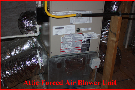
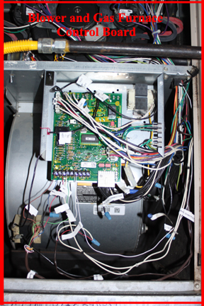
In the image blow, the gray sheet metal housing of the blower unit can be seen where the motor is mounted on the right side.
The computer board seen in this image is the blower unit control board.
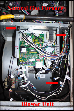
Although not obvious from image above, but once the furnace control board is removed, the entire blower assembly can slide out of the blower unit for motor repair or replacement.
The image below shows the large white connector going from the furnace control board to the actual blower motor
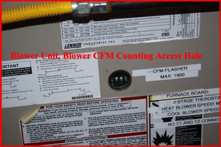
Not sure on every system but on my Lennox, there is whole in the sheet metal cover or the blower section that allows you to determine the cubic feet per minute (CFM) your blower fan is providing the output duct work.
With the blower running, looking into the hole to the right, you will see a green flashing light emitting diode (LED). If you watch the flashing LED, you eventually see it pause and then go out for a moment or 2 and then begin to flash again. Then next time, the LED pauses, if you count the number of flashes, this is the CFM of your blower.
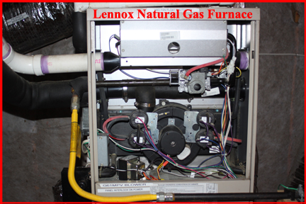
Blower Control: Every forced air system blower unit has some type of control board or connections panel. In a single zone system, a single thermostat might connect directly to the "control board" in the blower unit, simply turning "on" or "off" the blower. In a multi-zone system, thermostats will connect to a zone control board, which then connects to the control board in the blower unit. Finally, like in my case, my blower unit has a built-in natural gas furnace, which requires some control board functions.
My gas furnace sits above the actual blower and blower control board.
In my case, the blower control board must also control the natural gas furnace: respond to calls for heat by supplying pilot light natural gas; sparking the pilot light gas; sensing the pilot light is actually burning; turning on the first burner tube and again ensuring it is actually burning and then finally, depending on if heat is still be called for, supplying natural gas to all other burner tubes.
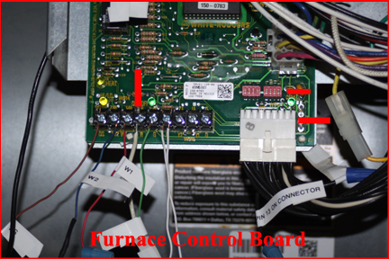
The image below is for my blower control board. It has connections to the gas furnace above, connections to the blower motor and connections to the zone control panel. Note that in my case, it does not have connections to any outside equipment, such as the air conditioning condenser.
Blower Not Running: There can be various reasons for your blower not to run when it should. Before calling a technician be sure: the circuit breaker providing power to the blower unit has not "tripped" out; make sure the emergency switch located somewhere near your blower unit is not in the "off" position'; make sure the circuit providing power to the zone control board has not tripped out; the thermostat does not need a battery change and set to correct heat or cool state?; check if the pan under the blower unit has water in it and if the float valve installed has shut the unit "off" and finally, if trying to cool, if the coil unit in the blower unit gets too cold, the zone control board will shut down the outside compressor and the blower unit. This last will probably only happen if refrigerant in the AC unit is low.
More Topics on Zone Forced Air HVAC