Shared Knowledge
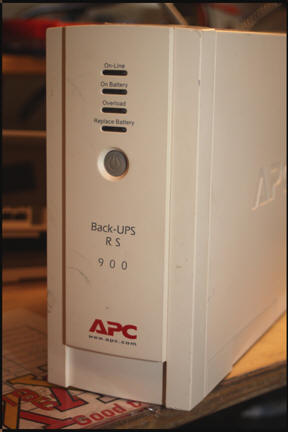
"APC RS 900 UPS - Getting Inside"
17 February 2014
Summary: it is not hard to get inside an RS900 for visual inspection but I could not locate an electrical schematic for the unit.
Background:
The first APC RS900 UPS I bought was off eBay and seller claimed it was in working condition.
Came with battery pack installed but would not turn on.
Removed battery pack (no little feat as batteries had swollen) and installed new and seemed to pass power-in self test.
Hooked a cable television (CATV) amplifier to it and all appeared well.
About one week later, RS900 sounded alarm and said battery pack needed replacement.
Removed battery pack and found both batteries discharged!!
Obviously RS900 was not charging batteries correctly.
Thought perhaps that if I went inside, I would discover some visual evidence of a bum component (charring or bulging capacitor).
Note here: the only real way to verify the APC RS900 is properly charging the battery pack is to hook it to a computer and run APC's PowerChute, free, application. Using this application, you can discharge the battery pack and then watch how the pack is charged or not charged.
Getting inside:
It is not hard to get inside the RS900.
Unplug from wall outlet and remove plugs for any devices plugged into RS900.
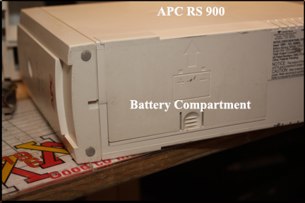
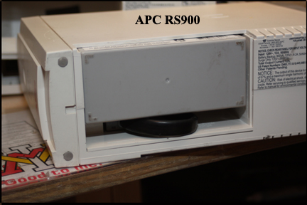
Remove battery pack.
The top half of the enclosure is what comes off the bottom half.
Remove the screws in the rear panel.
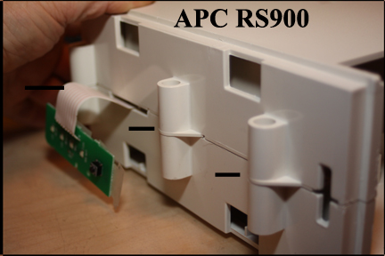
In the front, the front panel is snapped into the enclosure.
You will have to insert a flat blade screw driver or knife and pry the front cover out of the notches it is latched into in the top enclosure.
With the front panel loose from the top of the RS900 enclosure, remove the 2 screws holding the top and bottom half of the enclosure together.
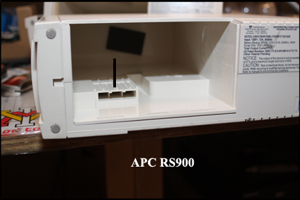
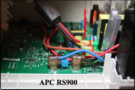
Now lift up the top half of the enclosure very carefully and expose where the battery cable connects to the circuit board.
Note here that the cable that runs from the connector in the top half the enclosure to the circuit board is very short and if you pull up to hard or quickly, you might damage the upper enclosure connector or the connectors on the circuit board.
I found these connectors to be tight down on the circuit board and you may have to use needle nose pliers to get the 3 wires off the circuit board.
Note here that the circuit board is well designed and well annotated meaning that wherever a cable attaches to the circuit board, the color of the wire is actually printed on the circuit board.
You should now be able to lift the top half of the enclosure off the bottom half.
The image below shows the rear of the enclosure with the top half removed.
Although not shown in any image here, there is a very large, heavy transformer located in the rear, bottom of the enclosure that simply sits in the enclosure.
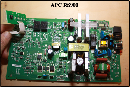
Below is the circuit board of the APC RS900 removed from the chassis.
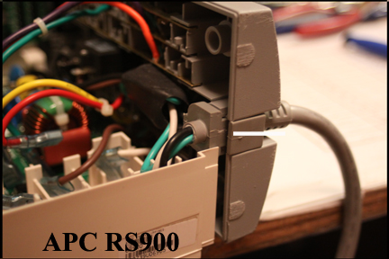
Removal is not difficult be does involve removing various wires from the rear of the board that go to the rear panel.
The circuit board is simply "snapped" into the bottom enclosure.
If you want to remove the circuit board from the enclosure, look carefully at the tabs on the bottom half of the enclosure and how they line up with cut-outs, other, in the circuit board.
Repairs:
As I said at the beginning, I went inside the APC RS900 because it was not charging the battery pack correctly.
Once inside, I found no visual evidence of trauma like charring of a component or any capacitor bulging at the top.
What to do??
From visual inspection I found that APC used (2) 12volt automobile type fuses soldered to the motherboard.
I checked these with a continuity tester and they were fine.
Looking the board over, I looked for capacitors (seems like the first electrical component to fail in any electronics) and found all 24 volt direct current (VDC) capacitors of which I found 2.
I ordered replacements (ebay, exact specification as defined on capacitor) and removed old and installed new.
Upon testing, no difference to incorrect charging of battery pack.
Unable to locate a circuit schematic, I was left trashing this unit (sad, bummer).
Note: APC does not service the RS900 and I could find no Internet-based company that will repair for you.